We will talk about game video (IIP) of the second generation, made on the basis of two BIS in buildings QNP (HH, HH 160 and TA-06W, TA-06S - 128 the conclusions). Besides them, the TRS Board placed two chips of RAM video memory HM53461ZP-12 and the transducer signals R, G, in the composite video standard PAL KA2197D or CHAR (using the same chip passes an AUDIO signal). As in other TRS, to stabilize the voltage applied microcircuits integral stabilizer 7805.
For Troubleshooting you will need avometr and high impedance headphones. Enabling the adapter into the outlet, measure the DC voltage (9... 14) releasable connector included in IIP (plus this voltage - external the contact plug, and the "minus" - to internal).If there is no voltage, look for fault: in the first place, breakage of the wires connecting the cord, and if they are intact, - in transformer. If there is voltage with dock connector TRS, turn it on and check the voltage (+5 V) at the appropriate contact Board with connectors.
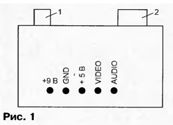
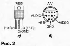
In Fig. 1 shows a view of it from above when it is removed the cover IWP; here: 1 - connector network adapter; 2 - socket "AUDIO/VIDEO". The presence of voltage indicates that the integrated stabilizer the 7805 voltage is OK. Otherwise, check whether there is the voltage at pin 3 of the chip (Fig. 2,a) and voltage of 9...14 In its output 1 (both - relative to output 2). No voltage at pin 3 if voltage at pin 1 indicates that the chip was released down and must be replaced (it is permissible to use domestic CREA, CREW).

If there is voltage +5 V on the CPU Board connect to TRS modulator, TV, known-good cartridge and joystick. Turn on EMU and start the game by pressing the "Start" of the joystick. If the game has started, the repair is completed, otherwise, the Troubleshooting will have to continue.
Suppose, after starting the game there is no picture on the TV screen (both high and low frequency) or there is a picture but no sound. In the first case, it is necessary to check whether the VIDEO signal at appropriate the pins on the card (Fig. 1) and sockets "AUDIO/VIDEO" (Fig. 2,b). The presence of this the signal can be judged by the distinctive roar with the frame rate in head phones connected to these pins and GND (GND). Similarly, on these contacts control and AUDIO signals.

Next check comes whether the VIDEO signal to pin 20 of the chip KA2197D (SHAR). Making sure in the presence of +5 V on its conclusions 12 and 19 (relative to pins 1 and 24), connect the headphones to the output 20 and GND (GND). If rumble with the frame rate is not listening, the chip is defective and should be replaced. If no chip is possible the use of signals R, G, b and SYN (they are supplied respectively to terminals 2, 3, 4 and 10 chips), served on a TV that has this sign.
The presence of AUDIO signal check at pin 9 of this IC. In the absence of signal in some cases (at break in the chain of this conclusion) valid pairing him with a pin 8, whereby the sound restored.
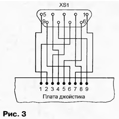
For "continuity test" the wires of the connecting cable of the joystick with an ohmmeter you can use the wiring diagram shown in Fig. 3 (fragment joystick shows the side mounting of the chip-droplets", and the socket - with the side of the mate).

Author: Zheleznov, Gornozavodsk Perm region.


