When shooting Amateur videos is not always possible to obtain sound support good quality and content. For its correction when overwriting with of the camera to the VCR and was developed for review device.
Audio mixer allows you to apply to the audio input of the VCR signal as a video camera, and with the additional sound source, for example, the player or microphone (the latter is better to use with your amp), and provides overlap from one signal to another. When needed, the can increase the signal level from the camera to 10 dB.
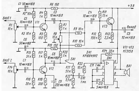
Schematic diagram of the device shown in the illustration.

The signal from the video camera serves on input 1, but with additional audio source - 2. With engines appropriate adjustment resistors R1 and R14 through capacitors C2 and C7 the signals are fed to amplifiers collected on the transistors VT1 and VT2 respectively.
The amplified signals pass through a controllable divider R7R8R20 on the mixer, made resistors R9, R10. It is through the capacitor C4 is loaded on the emitter follower is made on the VT3 transistor. The latter reduces the output impedance of the device.
Controllable divider R7R8R20 represents the ratio regulator filed the inputs of the device signals. The adjusting resistor R8 mutual change the levels of signals from the camera and an additional source of sound coming on the output of the audio mixer.
In the case that the regulator of a relationship R7R8R20 skips on the record only one of signals (in the extreme positions of the engine variable resistor R8), to control the second signal, the device offers a power amplifier assembled chip DA1, the opposite phase outputs of which are connected a sound projector - dynamic head of BA1 or head phones, which are even more convenient. The monitored signal select switch SA1. The divider provides R21R22 the required volume level.
The device can be powered from AC or from a galvanic battery ("Crown").
In the audio mixer used fixed resistors MLT and variable resistors SDR-4m. Capacitors C10, C11 - km-6 or similar, the remaining oxide - K50-35. Transistors CTV interchangeable on any of the series KT315, KT3102. Instead of chips CRON you can use AKRON. They are discussed in the article by D. Turchinsky "Audio power amplifiers AKRON and KRON ("Radio", 1998, № 5, p. 61, 62). You can use other chips, for example, CAN.
Establishing device is to receive a voltage of 4.5 V at the collector transistor VT1 selection resistor R2 and the desired volume level in the sound projector BA1 selection resistor R22. However, before to achieve last, you need to set the nominal input signal levels, and why serve as variable resistors R1 and R14. To make it easier experimentally at the hearing on the volume of the sound reproduced on the TV. First, remember subjective volume level when listening to some the television program. Then to the audio input of the TV signal with the output of the audio mixer, pre-connected to its inputs the signal sources and incorporating them. Translating the slider of the variable resistor R8 alternately in the first one, and then in the other extreme position, choose the video camera signal (engine on the scheme below) or with an additional sound source (engine top), and resistors R1 and R14, respectively, place the same subjective level the volume, and when listening to TV programs.
Author: Vladimir Gurevich, Rostov-on-don


