Many users of different face video with complaint to TV television signals from several sources (two or three antennas, VCR, etc.). For its solution the author proposes to apply the automatic diode switch.
The development of Central and local broadcasting, expanding the use of video technology lead to the need automatically switch the TV signal sources when the selection of appropriate programs. Switching unit three inputs such sources of mechanical relays with electronic logic control it was used when expanding the capacity of the block selection SVP-10 and discussed in the author's article "12 programs instead of 6" ("Radio", 1997, No. 4).
Of course, switching inputs, mechanical relay is not the best option due to parasitic capacitance and inductance of the contacts. It doesn't matter when differing frequencies of the programmes. But if I receive the same program by different antennas, for example, direct and reflected beam, relay switching becomes unacceptable due to the addition of the main and spurious signals. For the same reason, to be unsuitable and the adder signals with different antenna inputs.
The problem is quite easily solved using switch on the switching diodes, opening a work log and blocking outside. This algorithm in combination with small capacity closed diodes (0,5...1,5 pF) and low differential resistance open diodes (0,5...5 Ohms) allows you to better suppress interfering signals. In their selection should be guided by what is best parameters diodes have CDA, KDA and a little worse - KDA, KDA, KDA. However, you can try other high frequency or pulse diode with close to the specified values of the parameters.

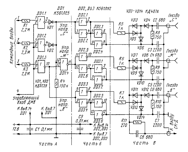
Schematic diagram of the proposed switch inputs shown in the figure. Antenna connector "C" (local television) connected to the TV, if you select a block SUP-10 programs on command inputs 1 and 2, the slot "B" (signal high frequency) - when selected program command input 3. When selecting programmes with inputs 1-3, a television signal received through the antenna socket "M" (Central TV). Control input 4 provides the binding of switched sources to the UHF range. Resolution the switching in the first two cases is a coincidence levels 0 in command and control inputs, and the third is their mismatch.
DD1 chip generates control voltages and chips DD2, DD3 commute diodes VD3-VD14. At zero control the voltage "C", "M" or "b" open diode (VD6, VD10 or VD14) closes the signal on the common wire, and closed the diodes VD3 and VD4, VD7 and VD8 or VD11 and VD12) prevent it from passing to the input TV. When a single control voltage state of the diode is changed and the signal passes through the switch almost without loss.
To reduce the parasitic capacitance and inductance the diodes and associated them capacitors raspalaut directly on the petals of the antenna nests with minimum amount of conclusions. The blocking capacitors C3, C5, C7 is better to use Leadless or after desoldering the existing conclusions. Parallel connection of inverters circuits DD2 and DD3 applied to increase the current through the diodes, in our case equal 10 mA.
Placement and connection of the parts And devices are the same as narrated in the above article. Part B (printed circuit) and (point wiring) are located close to the antenna jacks on the TV and connected to a part of A five-wire harness.
The device provides highly efficient switching of sources of TV signals. As the interfering signal is significantly suppressed, absolutely no overlay images on television and the resulting specific distortion.
In conclusion, it should be noted that the considered switch it is easy to adapt to other contexts of reception and other devices the choice of programs on TV. Only need to change the input the logic of work and the number of Executive channel switching.
From the editor. For proper operation of the switch it is necessary that the input impedance SC-L DC not greater than 75 Ohms.
Publication: N. Bolshakov, rf.atnn.ru


