


")

For those wishing to take the program on a decimeter waves (UHF) is proposed to repeat another option indoor antenna and Converter. They have good performance features, easy to manufacture and develop.
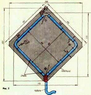
The UHF antenna depicted in Fig. 1, is an incomplete zigzag antenna, for the manufacture of which used 75 Ohm cable. At a distance of 240…245 mm from the end of the cable at the bend section And removed the outer shell and braid in the range of 10 mm. On the plot B is removed only the outer insulating sheath of the cable in the range of 15 to 20 mm from the end and at a distance from him 480 490…mm Shielding braid on this site is held tightly, providing electrical contact.
For fastening the leaf antenna and improve the contact on the plot B cables are secured to an insulating carrier plate antenna brackets of tinned copper wire of diameter 1 mm. Inner conductor at the cable end is left free. The entire blade antenna is also mounted on the plate staples from wire with a diameter of 1 mm. Carrier plate is made of organic glass, but may be made of textolite, Micarta, dry plywood, etc. with a thickness of 2.5…5 mm.
In the case where the reception of the reflected signals interfere with and need to increase the antenna gain, its canvas add a reflector in the form of a rectangular sheet of aluminum or other metal with a thickness of 1.5…2 mm and dimensions 330x200 mm. It is attached on the four pillars of a dielectric material (hard rubber, Micarta, organic glass) with a diameter of 8 and a length of 100 mm to the insulating plate antenna with M4 screws (holes in this plate and the reflector is provided). The antenna is placed on a rack with a height of 300…400 mm with base.
Converter, schematic diagram of which is shown in Fig. 2, provides the conversion of signals in the UHF signals on one of the channels (4 or S) MB. It contains aperiodic RF amplifier (transistor VT2), the inverter (VT1) and heterodyne (VT3).
From the antenna via connector XW2 and capacitor Sz RF signal is supplied to the emitter of the transistor VT2 is connected in the circuit ON the amplifier
RF. This RF amplifier eliminates the passage of the lo signal to the antenna. From the amplifier the RF signal enters the emitter circuit of the transistor VT1 Converter. Resistor R3 eliminates the possibility of self-excitation Converter and the RF amplifier, improves the conversion process.
The inverter transistor VT1 is performed also according to scheme ABOUT for the configuration of the output circuit L1C1 have practically no effect on the frequency of the local oscillator. The DC of the transistors VT1 and VT2 are connected in series.
The local oscillator is assembled on the VT3 transistor according to the scheme of capacitive treatacne feedback through aboutnomoney diode VD1, who also served as the setting item of the Converter. When you move the cursor of the variable resistor R6, the voltage changes smoothly on the base of the transistor VT3, the current through it, and therefore, the reverse voltage on the diode VD1 and the tuning frequency of the resonant circuit of the local oscillator, which serves as the unbalanced transmission line L2. The lo signal (the voltage drop on the findings of fact of the capacitor C5) through the condenser comes With 4 Converter.
The antenna connected to the MB connector XW1. Signal MB with her through the contacts of the switch SB1.1 in position "MB", the cable and plug XW3 is input to the TV. When you switch the switch SB1 to "UHF" on the Converter through the contacts SB1.2 is energized from a power source GB1 (led lights HL1), and from the output of the Converter through the contacts SB1.1 received the MB signal also passes through the plug XW3 to the input of the TV.
In the Converter applied to variable resistor SP-04 (R6) and constant MLT, under-postperestroyka capacitor PDA (C1) and constant M, M1500 or CD-1. Coil L1 wound on the resistor R2 and contains 12 turns of wire PEL or sew with a diameter of 0.3 mm with a branch from the fourth turns, starting from the output connected to the common wire.
Details of the Converter are available on the circuit-a circuit Board from a two-sided foil fiberglass with a thickness of 1.5…2 mm and dimensions H X96 mm Drawing it together with the housing and the partitions shown in Fig. 3 (triangles it depicts places soldering and wires to foil Board or its grounds, points - soldering conclusions on the hard elements).
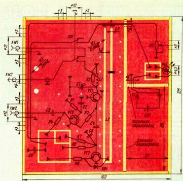
Fig.3
Strip line L2 and the mounting pad is embedded in the circuit Board cutter with a thickness of 1.5 mm line Width equal to 3 mm when using fiberglass 2 mm thick (if it has a thickness of 1.5 mm, the line width is 2 mm, and the width of the cutter-0,5…1 mm). In hole Board with a diameter of 1 mm inserted segments of tinned copper wire with a diameter of 0,8…1 mm and soldered on both sides of the Board. Transistors VT1 - VT3 installed in the holes of the Board with a diameter of 6 mm. on the other hand they are closed circles of foil or thin copper sheet, soldered to foil Board, so as not to push the transistors in the operation inside the body of the Converter.
The side walls of the housing are made of one-sided fiberglass thickness of 1.5…2 mm, the foil inside. Two side walls are sized H mm and the other two H mm, long baffle - H mm, short - H mm. the Printed circuit Board is located 2 mm above the lower ends of the side walls and soldered them on both sides. Places touch the side walls, partition walls and boards with each other carefully soldered.
The switch SB1 - P2K. The findings of the locking mechanism is shortened to 1 mm. It is installed with a clamp to the side of the circuit Board and fastened through the sleeve by screws to the side wall of the housing of the Converter, as shown in Fig. 4. Cable length RK-75-3-31 from switch to plug XW3 - about 1 m, but can be any length, depending on the convenience of the Converter. The cable is attached to the circuit Board with metal bracket and two screws MOH. Converter is closed by a lid made of the same fiberglass dimensions H mm.
When establishing the first Converter to measure the current consumed them. To do this, connect a milliammeter in series with the power source. The current must be equal to 5 mA. Then touch a metal object to the output collector of the transistor VT3. The current should fall to 2.5…4 mA, depending on the position of the variable resistor R6.
After that, moving the jumper on the strip line L2, achieve the appearance of a stable image on the fifth or the fourth channel MB (UHF antenna must be precisely directed to the transmitting station). And, finally, rotating the rotor of the capacitor C1, and configure the circuit L1C1 and receive the maximum signal level, judging by the picture on the TV screen.
Fig.4
The Converter can be powered from the TV via a simple power source, the circuit of which is shown in Fig. 4, and circuit Board - in Fig. 5.
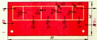
Fig.5
Board is placed inside the TV. Resistors in the source - MLT, the capacitors C50-6. During independent performance Converter you can use any small mains transformer with the secondary winding voltage of 6.3 V At a load current of 20 mA.
Author: M. Iliev; Publication: N. Bolshakov, rf.atnn.ru