


")

When viewing videotapes of the recorder to the TV can be connected via antenna input or use a low-frequency (LF) video input TV. In the first case, the double conversion of the video signal. In the tape, the video signal is converted to high frequency, as happens in the TV the inverse transform. As a result in the signal being distorted and increases the level of noise that is noticeable in the image quality on the TV when watching the videotapes.
There are other inconveniences and problems, especially when connecting imported VCRs.
There is a second way to connect the VCR using WOOFER video input (video card) to TV. Unfortunately, the majority of domestic TVs, especially the early editions, do not have such a device, though provided for the place for installation.
In Fig. 1.1 shows a diagram of a simple adapter for the TV. The scheme will not need to turn on and off as it turns on in operation automatically when the signal from a connected VCR. The device consists of a switch of the video signal on the chip D1.1 and the transistor VT1, key changes the time constant of the sweep at D1.2, and the selector clock on VT2 and VT3 (used for automatic mode work with the VCR). The signal output from the tape recorder through a separation the NW and capacitor emitter follower enters the module channel on the TV. The constant component of the voltage at the emitter of VT1 detected in the radio channel the TV and to the input of the video amplifier of the TV only receives the signal from the VCR.
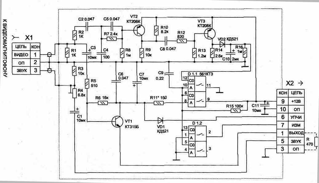
Fig. 1.1 (click to enlarge)
The audio signal from the VCR through the condenser C1 and trimmer resistor R4 is supplied to the audio input of the TV. Resistor R4, when the VCR you can adjust the volume of sound the same, as with television programming. A preliminary review of the collected the scheme is convenient to hold, as shown by the pulses (T = 64 μs, t= 58 MS) amplitude of 0.5 In from the generator to the input sockets X1/1, and control their appearance on the emitter VT1 without distortion. For this to emitter need to temporarily connect the resistor R resistance 470 Ohm (shown by a dotted line in the diagram). The constant component the voltage across the resistor should be about 6.5 In (to control the oscilloscope). This voltage ensures the locking of the module channel on the TV at work with the VCR.
Diagram of the adapter is designed for installation in TVs models ZUSTST. Structurally, the entire device is placed on one a printed circuit Board that is installed into the TV to charge the A1 module channel (ISC-2-5) into the connector XS, if he is on the Board, or to appropriate podpisyvaetsya the connectors on the location of this connector. Socket X1 (any type) is fixed on the back of the TV and is connected to the card adapter two shielded wires with a length of about 40 cm.
In conclusion, we note that this video card can to use and simple to connect home computer to the TV. For this input to the adapter via a current limiting resistor 0.1…1 kOhm (to pick up when connecting) served sinhrosmes signals output from the computer.
Publication: www.cxem.net