


")

Unlike the above schemes, described below, the circuit device with signal transmission over balanced lines. In this case, the noise level of the amplified signal are masked to a greater extent.
Schematic diagram of the microphone amplifier is shown in figure 33.
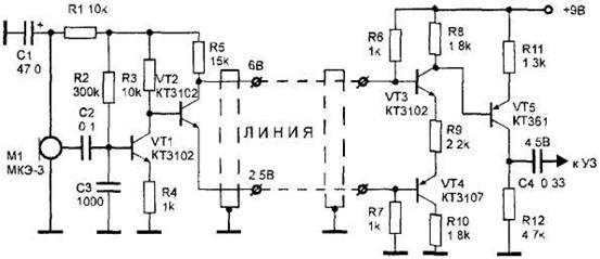
Figure 33. Remote microphone with power from a three-wire line.
The signal taken from the microphone Ml type FEM-3, "Pine", is fed to the amplifier assembled on the transistor VT1. The transmission coefficient of the cascade is performed on the transistor VT1, approximately determined by the ratio of resistances of resistors R3 and R4. The signal amplified by the transistor VT1, is supplied to the base of transistor VT2. And since the phase of the signal at the collector of transistor VT2 is opposite to the phase of the signal on the emitter, and the signal line, too antiphase.
Input stage the right part of the scheme, collected on transistors VT3, VT4, is an adder with a phase shift of 180°. Thus, the anti-phase signal is formed in the phase and is formed at the output useful signal with twice the amplitude. And encountered the same phase noise and interference in each of the wiring lines cancel in the adder. The total signal is supplied to the base of transistor VT5 type KT361. This stage has a gain of 4. With loads of cascade, resistor R12, the signal is fed to the terminal the audio frequency amplifier or tape recorder.
The device uses type resistors MLT-0,125. Transistors VT1-VT3 can be KT315 type and CT, transistors VT4, VT5 - KT361, CT. As the microphone Ml can be used by any electret microphone with built-in amplifier.
Amplifier setup is selecting a resistance of the resistor R7 and the need to control the voltage indicated on the schematic diagram.
To connect external microphone required shielded cable with two inner conductors.