Since losses are reduced, the amount of horizontal beams of the antenna can be reduced to two.

Fig. 1
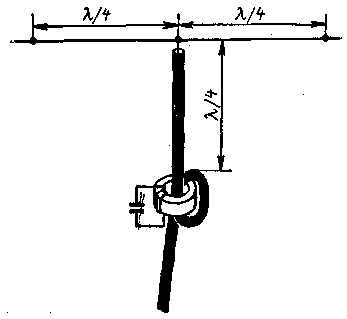
Inverted Ground Plane for one band is shown in Fig. 1. Cut the antenna cord, forming rays stretched nylon fishing line with a diameter of 0.9-1 mm.
By the middle of the segment connected to the inner conductor of the coaxial cable. Shell remains free and must be well insulated. The cable is discharged vertically downward or inclined in a plane perpendicular to the line. On removal of a quarter wave from the upper end of the cable is on the "tube", blocking the path of the high frequency currents on the outer surface of the cable sheath.. "Tube" is an inductor associated with a resonant circuit, which introduces a large coil resistance, that is tuned to the frequency of this range. For the device "plug" cable once or twice through the ferrite ring large diameter (preferably CHH ferrite VC-2), which also wound contour coil connected to the capacitor.
Contour coil can also be done in the form of a circular frame of two or three turns tightly compressed well insulated wire(suitable thin coaxial cable with external insulation made of polyethylene). The feeder in the right place roll per revolution of the same diameter as the contour coil. Round and contour coil make each other close and fasten with tape.
The condenser must be sufficiently high and mighty: the power transmitter 100 W voltage it can reach 400-500 V.
The estimated contour of the coils of the stranded wire of diameter of 2 mm are shown in the table.
Range, MHz
The number of turns
Wire length, cm
The capacitance, PF
The figure of merit
7
3
160
150
260
14
2
115
68
230
21
2
80
47
210
28
2
60
36
265
On the characteristics of the cable "plug" is not affected because it is outside the field of internal conductors. Below the tube surface of the cable is almost neutral, so the length of the feeder is not limited and it can lie on the roof, to touch the walls of the house, etc.
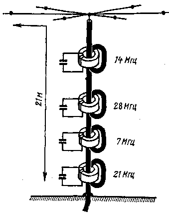
From single-band antenna is easy to move to a multi-band. This should be in the right places along the length of beams and cables to install "plug" on the appropriate ranges. You can also replace the system of tubes by a system of beams of different lengths, connected in current antinodes. The author chose a combination of the horizontal portion in the form of rays of different lengths, while the vertical set of "traffic jams". The scheme of such antenna on five ranges shown in Fig. 2.

Fig. 2
As can be seen from the figure, the horizontal part consists of three pairs of beams with a length of 10, 5 and 2.5 m each (full scale antenna - 20 m). The first pair - ranges 7 and 21 MHz, the second for 14 MHz and the third with 28 MHz. "Tubes" are located on the feeder at distances (from top): 7.5 m - 28 MHz (the length of the vertical part is 0,75 l, which gives an additional gain); 3,5 or (better) 10.5 m - 21 MHz; 5 m for 14 MHz, 10 m to 7 MHz. These sizes are approximate and should be specified when configuring. For operation at 3.5 MHz braid of the cable immediately after the lower tube grounded - connected to a metal fence or concrete reinforcement.
The input impedance of the antenna on four high-frequency ranges close to fifty ohms, so as the feeder is best to use a shielded cable with the same impedance. The input impedance in the range of 3.5 MHz largely depends on local factors and may exceed 100 ohms.
The tuning of the antenna is reduced to determining the minimum SWR on each band. Then move the tube by a distance proportional to the displacement of the minima and again to check SWR. Setting on 3.5 MHz can be performed either by the displacement of the point of grounding, or switching in the grounding circuit of lumped inductance or capacitance.
Author: Yu Medinets (UB5UG), Kyiv; Publication: N. Bolshakov, rf.atnn.ru


