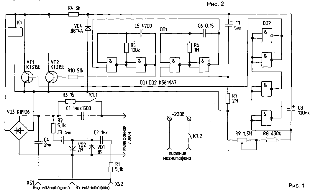
The proposed scheme (Fig.1) is a simplified equivalent autoresponders and informants.

(click to enlarge)
When you call pulse signal passes through the container 1 and the diode bridge VD3 on relay K1. The relay is activated. Through contact K1.2 closes the supply circuit of the tape recorder. Contact K1.1 closes the capacitance C1, and relays and circuit supplied DC voltage 12...14 V. self-locking Relay. Run the generator intermittent signals on the chip DD1 and a threshold device on the chip DD2. The signal from the generator is supplied to the base VT2, the load of which is the internal resistance of the telephone line. The operating time of the generator depends on the time of charge via C7 R7. A threshold device provides the desired time of operation of the tape recorder, which depends on the time of charge through C8 R8 and R9. When triggered, the device transistor VT1 opens and gives a lift" voltage to the relay. The relay is released, its contacts open, and the circuit enters standby mode. Chain R1, R2, C2, C3, VD1, VD2 is used to equalize the signal amplitude in the recording mode of the conversation on tape. She gently limits the signal with higher amplitude. The resistance R3 limits the discharge current of C1.
Details
The bridge using VD3 must withstand a reverse voltage of 150 V. When using another relay capacitance C1 may have to increase to 2...3 UF. In the scheme used relay RES 9 with weak return springs that gave the opportunity to reduce the operating current. You can use other relay with a coil resistance of 500 Ω... 1 kω and a minimal operation current.
Transistors VT1 and VT2 - type n-p-n maximum voltage 60 V (CT).
With proper installation of the device requires no adjustment.
Author: E. Rodionov, Minsk; Publication: N. Bolshakov, rf.atnn.ru


