Because of rampant telephone services in the near future does not threaten us, some of our compatriots have learned to solve their problems at the expense of neighbors. Connecting to other people's phone lines, call wherever you want. Those who became a victim of piracy, you know how frustrating to get unexpectedly increased phone bill. Of course, you can put your phone-caller ID functions with line protection from unauthorized access. But such devices are quite expensive, and for the use of a telephone station requires additional payment.
The most optimal in this situation is the use of special locking devices-locks. Unlike conventional blockers [1], these devices function as sort of a "barn" lock on your phone line, making it impossible as the correct set of numbers in a line, and the passage of the ringing signal. Normal operation of the telephone stations, such devices do not prevent.
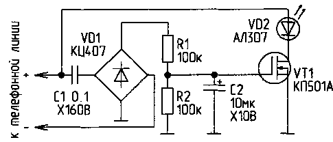
Scheme is the simplest of the castle is presented in Fig. 1. In the initial state, the capacitor C2 is not charged, and the transistor VT1 is locked. If you encounter an alternating voltage on the telephone line (dial or call PBX) voltage paradiselost of the capacitor C2 opens the transistor VT1, and a telephone line for a short time closes them.

Fig. 1
The charge of the capacitor C2 is stopped and it is discharged through the resistor R2. Transistor VT1 is closed. The phone line remains open until the next pulse. The disadvantage of this lock is that when it is turned on in the phone line requires correct polarity.
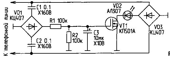
The scheme presented in Fig.2, contains more details, but free from the above disadvantage.

Fig.2
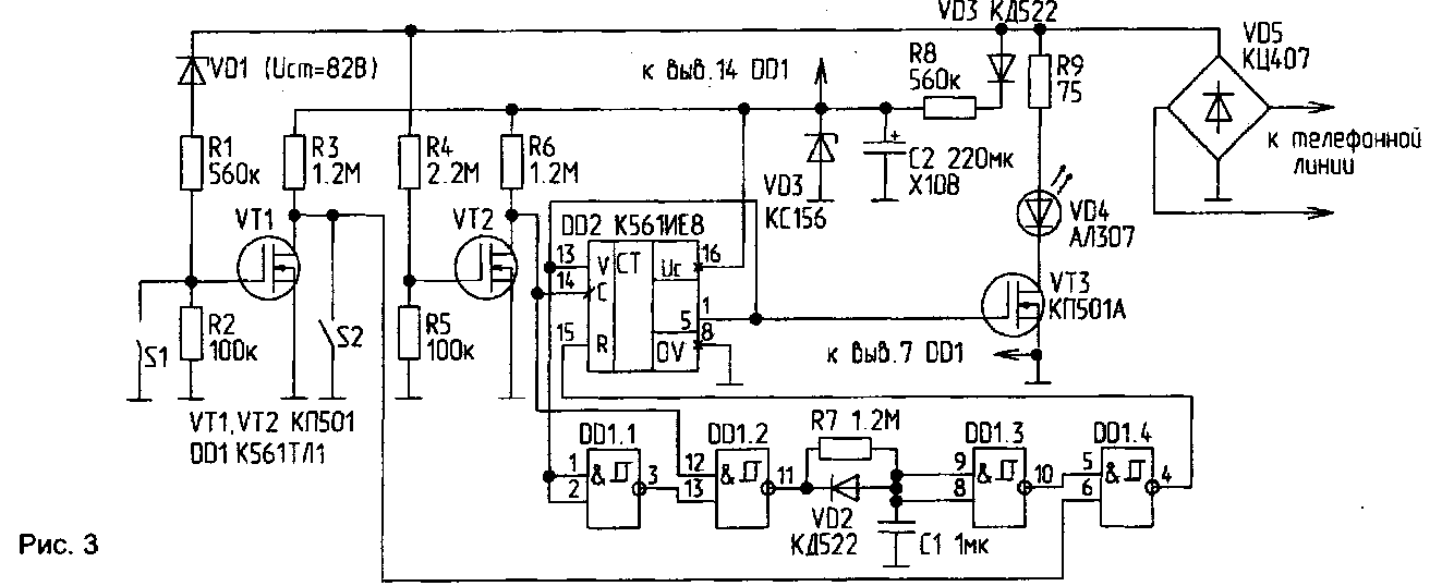
Life is not always required to "extinguish" a tone from the PBX. Often you want to "spoil" the only set of numbers. Locks, represented in Fig.1 and 2, this selection does not produce. Better lock depicted in Fig.3. It is powered from the telephone line through a resistor R8 and consumes from the line in the standby mode, not more than 0.1 mA. The Zener diode VD3 - parametric voltage regulator. The voltage pulses that occur on the telephone line when dialing or when the call signal from the PBX through the cascade transistor VT2 is received on the clock input (pin 14) of the chip DD2. After five pulses at pin 1 of the chip DD2 appears high level, the transistor VT3 is opened, and the phone line is blocked. At the same time, this high level is supplied to the enable input of the account DD2 (pin 13), and prohibits any further expense. A logic level " 1 " at the input element DD1.1 after a double inversion causes the output element DD1.2 high voltage level. The capacitor C1 is slowly charged via the resistor R7, and approximately 1 high level input element DD1.3 causes the appearance of a single signal level at the input R of the chip DD2. The counter is reset, the transistor VT3 is locked circuit comes in its original state.

(click to enlarge)
Cascade transistor VT1 only responds to the ringing signal from the PBX and serves to prohibit actuation of the "lock" signal from the call. The low level voltage from the drain VT1, acting on the pin 6 DD1.4, causes a high level at the input R of the chip DD2, i.e. the counter is held in the initial state. The user can disable or enable the passage of the tone from the PBX, using switch S1. Switch S2 is used to prohibit the operation of the entire device, when the owner of a telephone line to dial the number.
The only vimasuma circuit R7, C1, VD1 performs two functions:
defines the time of blocking the line when you turn on the "lock";
- in standby mode, forcibly sets the counter DD2 to its original state.
DD1 chip can be replaced by CLA. Transistors VT1, VT2 can be any letter A, B, b, the transistor VT3 is only with the letter A. a Light display incorporating locks can Supplement and also sound.
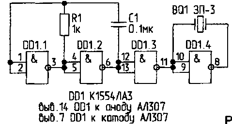
In Fig.4 shows the sound generator integrated into a chip 1554 series (analogue 74AC00N). Unlike series 561, microcircuits above series is operable at a voltage of 2 V.

Fig.4
The piezo oscillator BQ 1 is included in a bridge circuit. The generator voltage is generated at the led, i.e. the conclusions of the "Power" and "General" DD1 is connected to the anode and the cathode of the led in any of the schemes of locks.
Literature
Author: A. Mikhalevich, Minsk; Publication: N. Bolshakov, rf.atnn.ru


