


")

We offer telephone switchboard (aka micro-PBX) is a a device that allows you to connect one telephone line to up to five devices (without their mutual influence on each other), having a set of additional service opportunities. Without a certificate of compliance this switch can be connected only those telephone lines that do not belong to the public domain (for example, PBX). To connect the switch to the telephone network for General use, you must obtain a certificate.
The device is based on a microcontroller PIC16F84-04/P firms "Microchip", the program determines which all other nodes of the switch. The device provides a locking phones, not participating in the conversation, indication of a busy phone, allows you to arbitrarily set the ringing phones and to divert incoming calls with music in the line. Also you have the option of restricting access to a telephone line by a three-digit job password separately for each phone (antipyrin"). For phones, installed as nevesinye, you can specify the number of dropped packages call, after which they will start to call.
The switch can be reprogrammed with any phone connected to it the device with the saved settings in electrically alterable a storage device (EEPROM) controller. Power is supplied from telephone line, current consumption up to 200 μa.
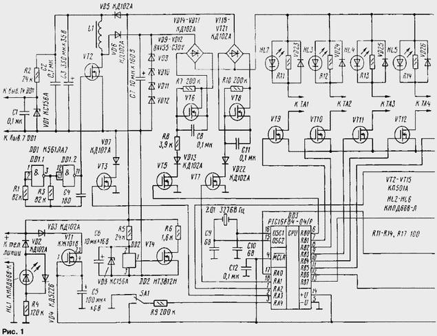
Diagram of the device shown in Fig. 1. In the initial state, i.e. when stacked the tubes on the phones and in the absence of an incoming call, the program the processor monitors the status of the sensor call R15R16 and the current sensor phones R18VT16. At this time, the telephone sets connected to the line, as the paddles current keys VT9-VT13 enjoyed a high level. On the other gates of the field transistors - low level. For example, a telephone set connected TA1 the following circuit: positive conclusion of the telephone line, a diode bridge VD18 - c VD21 open transistor VT8 in the diagonal, the resistor R11 and diode HL2, transistor VT9, resistor R18 and the junction, the base-emitter VT16, common wire (negative line).
When removing the tube from one of the phones through the junction between the base and the emitter of the transistor VT16 current begins to flow and it opens. The voltage at the collector VT16 changes from high level to low that program is registered of the processor. Then, the controller alternately turns off the phones, tracking level on the collector VT16. Once disconnected the phone off the hook, the voltage at the collector VT16 again will change from low to high level and the program will be able to determine this phone. Further, it again connects to the line, and the other phones are turned off.
If the device is in the "antipyrin" (it depends on the configuration EEPROM CPU), then when you pick up the handset on the shutter VT14 goes to a high level. Transistor VT14 open, thereby connecting the Zener diode VD27 to the line. When this dialing is impossible, because at the time of typesetting pulses the line current will flow through VD27, and switching relays on the PBX to trigger will not be. However, the controller remains able to read dials with the current sensor phones, i.e. the collector of the transistor VT16.
Thus, the user is given the option to enter a three-digit the password that the controller will be compared with the values stored in EEPROM, and in the case of matching the high level to the gate of VT14 will change to low. To inform the user that the password was typed correctly, the device gives a line confirmation beep (through the transistor VT15 and resistor R19). In that case, if the entered password does not coincide with the desired dialing in the line cuts out. The processor waits for the moment when the tube is laid by monitoring the state of the current sensor phones.
The transition in the programming mode possible settings, if before lifting the handset switch the toggle switch SA1 in a position in which at pin 3 of the controller DD3 will be a high level. In fact, this is exactly the same mode as the mode "antipyrin", except that instead of the password should be recruited programming codes.
On the resistive divider R15R16 assembled sensor of the incoming call. When you are prompted make a call, there is a high level across the resistor R16, which is monitored a processor. Then the phones installed as nevesinye (if any), turn off ringing and ringing phone. In the pauses between transmissions call monitored the status of the current sensor phones. After removal of the tube is determined by the used phone and the other devices are turned off. Further the program waits for a set of numbers, which is the telephone number to which you want to forward the call.
For example, the incoming call is answered with TA2 and should be forwarded to TA4. At TA2 need to press the number 4. After reading this figure the controller beeps in line, disables TA2 and connects TA4. Then on TA4 receives the signal of the call.
There are several ways of forming the ringing voltage with preservation connection. The simplest of these next. Call the phone connects to line, and the line is energised and de-energised for a small load (about 50 Ohms) with the help of the current key with a frequency of 25 Hz. During disconnection a voltage spike occurs, the amplitude of which depends on the inductance of the relay PBX and reactive resistance of the connected phone. Thus, when the voltage in line 60 can be formed In a tone amplitude 60…80 V. However, the ringing voltage will not call all phone the vehicles. For example, telephones with electronic zvonkova chain can not call quite or call quiet. If you increase the frequency of the ringing signal to 70…80 Hz, we will call most of the electronic phones, but will stop calling phones with mechanical bell. Also there are two more big drawbacks: first, the person at the other end of the line will hear a very strong and unpleasant sound, and another disadvantage is the significant obstacles which may to be transmitted during a call. Increase of ring strain can, if in series with the line through restrictive and isolating circuit to commutate the inductor. In this case, you get to ring all phones, however, this method is not devoid of these two shortcomings.
In the proposed design for the formation of the voltage applied challenge the simplest single-ended Converter, switching diode bridges with the transistors in the diagonal. The Converter consists of a master oscillator on the elements DD1.1, DD1.2, the switching transistor VT2, the coil L1, diode VD6, the storage capacitor C7 and restrictive Zener VD9-VD12. When applying a high level from the controller to the gate of the transistor VT3 Converter connects to the line. The generator on DD1.1, DD1.2 begins to operate at a frequency about 25 kHz. The key transistor VT2 commutes coil L1, and the cumulative the capacitor C7 and a voltage of 120 V, which limit the Zener VD9-VD12.
If we consider the example of the redirection of calls from TA2 to TA4, the algorithm of the controller will be next. After TA4 was connected to GND through an open transistor VT12, the shutter goes to a high VT7 level. Transistor VT7 open, and VT8 - closed. Thus TA4 is disconnected from the refrigeration output of the telephone line and remains connected to the cumulative capacitor Converter 7 via a diode bridge VD14-VD17 and transistor VT6. Simultaneously the Converter feed high level to the gate of VT3.
The controller then issues a two-phase square wave frequency of 25 Hz for paddles transistors VT5 and VT15. When they are low, TA4 connected to the inverter, when high - disconnected from him and is shunted by resistor R19 to discharge the capacitor zvonkova chain. Thus is formed the parcel the call duration of 1 s. the Current call is held by a current flowing through the Converter. Line voltage with about 15 In noise is not skipped. Current monitoring phone happens in the pauses between calls. Once TA4 pick up the phone, ring stop, the inverter will shut down. If not going to pick up, then after about 30 with the call will be redirected back.
The lack of interference when forwarding allowed to issue in line music an escort. To do this, together with the Converter connects the chip DD2 - driver melodies. The music in the line goes through the elements VT4, R6.
The CPU power is provided via the current stabilizer VT1. The voltage across it however, about 5 V. HL1 Led serves to indicate polarity. When properly connected, it glows shouldn't.
The switch is assembled on a printed circuit Board from bilateral foil fiberglass (Fig. 2). Coil L1 is wound on an armored core B18 wire PETV-2 with a diameter of 0.1 mm, it contains 100 turns.
Assembled device should begin working immediately, no adjustment is required.
Reprogramming is performed as follows. When stacked tubes at all phones toggle switch SA1 must be installed in a position in which the pin 3 CPU DD3 will be served a high level. Then from any phone need to lift the handset and dial the password to access the programming mode. In the attached "firmware" is the password - 21534. If it is spelled correctly, you will hear confirmation beep. Next, set one of the codes listed in table. 1, you can change any setting and, after confirming sound signal, hang up. "xxx" means any three-digit number. There the ability to set the number of packages call, after which even nevesinye the phones will ring. For this we need to type in a reprogramming mode H, where x is the number of dropped packages call. If x=0, nevesinye phones will not ring.
Table 1
Function TA1 TA2 TA3 TA4 TA Setting the password on intercity line 21+xxx 22+xxx 23+xxx 24+xxx 25+xxx Access to the line through a password 31 33 35 37 39 The line access number without a password 32 34 36 38 40 The phone rings on incoming call 51 53 55 57 59 The phone will not ring on incoming call 52 54 56 58 60A switch operable to PBX voltage 48…60 V, most of the coupled the lines on electronic exchanges (when working with pulse dialers).
Program the firmware of the PIC controller
Author: V. Kulakov, Rostov-on-don