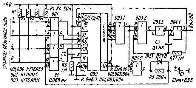
The device, a schematic diagram of which is shown in Fig. 1, generates any given number of pulses in the range of 1 to 10. It can be used in devices controlling the operation of digital components, encoders codes or commands, switches, etc.
From the known devices of similar purpose shaper is easy to build a small number of integrated circuits, as well as small (not more than 4.5 mW) power consumption, allowing it to be used in devices with Autonomous power supply. The pulse repetition rate at the output of the shaper is from 0.1 Hz to 1 MHz (when specified on the circuit component values R7, C3 it is approximately equal to 10 Hz), duty cycle - 2.

Fig.1
The device comprises a driven multivibrator (DD3.2, DD3.3, DD4.1), counter (DD2), the element matches (DD3.1) and the node lock (DD1, DD4.2, VD13).
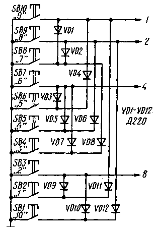
The number of pulses in the parcel is defined entered into the meter (using the encoder, binary) number, which is up to 10. To obtain a series of ten pulses, the counter enter the number 10 (about the formation of sending pulses in this case, discussed below). The last pulse of the parcel moves counter to the zero state (0000), and the output element matches a voltage is applied, prohibiting the operation of the multivibrator. The binary code signals corresponding to the predetermined number of pulses can be obtained by using a diode encoder, the scheme of which is shown in Fig. 2.

Fig.2
At the time of power appearing at the resistor R6 (see Fig. 1) when charging the capacitor C2 positive pulse sets the counter DD2 to zero (0000). At the same time the output element of coincidence DD3.1, there is a high logic level, prohibiting the inclusion of the multivibrator and allows parallel recording of binary code signals into the counter (inputs SI, S2, S4, S8) through the elements of the chip DD1 node lock. Upon receipt of these signals (pressed one of the buttons SB1-SB 10), the counter is set to the appropriate state. The output element DD3.1 appears a low level, creating conditions for triggering of the multivibrator, and the output of inverter DD4.2 - high level, which quickly charges the capacitor C1 through the diode VD13 and prohibits the entry of signals across the chip DD1.
The multivibrator generates pulses with a repetition frequency determined by the circuit R7C3. They arrive at the input of the counter DD2 and flip him. As the entrance A2/10 is connected to the common wire, the counter CIE works as a decade in which the state of 9 (1001) of the first and fourth triggers (and therefore the entire counter) is set to the zero state. At the outlet of the element DD3.1 once again there is a high logic level, the multivibrator is turned off, and the capacitor C1 discharges through the resistor element R5 and DD4.2. After a time determined by circuit R5C1. the voltage at the inputs of chip elements DD1 is reduced. level 0 is enabled, the following entry binary code signals into the counter. In other words, this circuit creates a pause between the series of pulses; without it, the multivibrator would work continuously all the time the button is pressed encoder.
A few words about the formation of a series of ten pulses. In this case, the counter is entered binary number 1010, corresponding to the decimal number 10. The first pulse of the multivibrator switches the counter to the state described by a decimal number 11 (binary - 1011). The next (second) pulse of the first and fourth trigger counter is set to the zero state, while the second remains in the unit that corresponds to the number 2 (0010). Further, the driver works in the same way as in other cases.
Also indicated in the diagram, the device can use any low-power germanium (for example D9 series) or silicon (D, CDA, CDB, etc.) diodes and chip series C. During installation, you must remember to protect circuits from static electricity.
The establishment of the shaper is to just install (selection resistor R7) of the desired pulse repetition frequency.
Author: Y. Erivan, Moscow; Publication: N. Bolshakov, rf.atnn.ru


