


")

The idea of creating a very light and portable directional LW antenna, made of wire and is stretched between the telescopic glass-plastic rods, though not new, but is increasingly attracting the attention of ham radio. German shortwave Paul Cornelius (DF4SA) proposed the design variant, in which on one frame of the four rods placed three wire antennas "wave channel" - two three-element in the ranges of 20 and 15 meters and one up in the range of 10 meters. Antenna, despite the portability and light weight, has a very good characteristics and KND the radiation pattern. Interest to the antenna DF4SA large, so with the permission its Creator, we describe the "Spider".
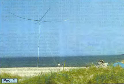
Introduction. Spider ("Spider") is a full-sized tri-band, very easy the antenna is constructed of glass-plastic rods, and wire. Total weight antenna about 5.5 kg makes it ideal for use in field conditions. A photograph of the antenna raised ten metre aluminium mast, it is shown in Fig. 1.
To suit any antenna telescopic light mast and rotator from TV antennas. Wind loads on the antenna is small. It is easy to built, and installed by one person. The envelope folded and Packed the antenna does not exceed 1.2 m. a Simplified (Directors and reflectors in one plane) sketch her designs are presented in Fig. 2.
The gain (amplification) G and the ratio of radiation forward/backward (F/B) "Spider" not inferior to other full-sized antennas, including stationary. Valid the radiation power in continuous mode is 2 kW. Basic data antennas are shown in table 1.
The main task during the installation of the antenna is to raise it to the maximum possible height. Antenna, even with a small gain, raised to a great height, give the best signal than the antenna with a big win, but it set at low altitude. Small the weight of the "Spider" makes his ascent to high altitude. Simplified and selection optimal installation location. The antenna is convenient to use in travel, set on the tops of the surrounding mountains, Islands, castles and towers and beacons even on any roof. This antenna favorably with conventional heavy tri-band "Bima".
The antenna Assembly is simple in design does not use any special complex elements. The absence of the setup procedure makes the antenna suitable for beginners. The cost of materials for the manufacture of the antenna is small, and you can still save on the mast and tilt.
The development of the antenna has contributed familiarity with original and elegant solution Dick Byrd (G4ZU), who offered his "Bird Yaga" - a three-element antenna "wave channel" with the V-shaped bent wire Director and reflector. It is also called the "Bow and arrow". However, in the literature was not descriptions multi-band designs, so DF4SA had to undertake independent development. After countless attempts of computer simulation, finally, managed to get a virtual antenna that meets business requirements.
Remained constructive, mechanical problem: the antenna should be lightweight but tough, to protect against moisture, have a duplicate electrical characteristics no matter how many times it was collected and dismantled. The Assembly is not supposed to be complex and require any special tools. All these requirements were met, and the author received a large fun watching how the antenna can be easily made violent storm when working out STSEE during the CQ WW CW CONTEST 2002.
Basic principles of antenna. Spider - wave channel for the ranges of 10, 15 and 20 meters. It is formed like three nested in one the other wire antennas are stretched to the common spider ("spider") fibreglass. These antennas, in turn, contain three elements for band 20 meters, three elements for a range of 15 meters and four elements for the range 10 meters.
The active element of the antenna consists of three individual dipoles for ranges 20, 15 and 10 meters, interconnected only at the point of supply. As a result no coils or circuits ("traps") in the design of the antenna is not used. The transition from the unbalanced coaxial cable to the balanced dipole used simple and broadband throttle device proposed W2DU. This makes the power supply system is very simple and reliable. No phasing lines or other matching devices is not required.
General sketch of the antenna (top view) and mounting dimensions of the elements (in centimeters) shown in Fig. 3.
The length of the wires (in centimeters) passive the antenna elements are shown in table 2.
It should be noted that these data are valid only in the manufacture of antenna made from copper or copper-coated wire with a diameter of 1 mm without insulation. Other types of wires, especially isolated, will require some correction sizes elements, which involved changing the velocity factor, which depends, in its the speed of wave propagation along the wire. The correction can to be necessary and when you use insulators at the ends of the wires of the antenna.
To withstand the exact dimensions of the antenna in its manufacture is very important. Error even in one centimeter (!) will lead to changes in parameters. It follows that the antenna cables should not stretch under load. It is best to use copper-plated steel wire, information about which can be found in [1]. When the first an instance of the antenna was made of a soft copper wire with enamel insulation, some elements in the Assembly-disassembly of the antenna stretched even 10 cm, causing the resonant frequency of the "left" and directivity deteriorated. Especially suffered from the ratio of the radiation.
The design of the active element is shown in Fig. 4. It consists of three dipoles which should be located in a vertical plane, strictly over other. As in the case of other multi-band dipoles, the farther they located from each other, the less they interact.
The distance between the upper dipole range of 20 meters and the lower band dipole 10 meters should be about 50 cm it is Also important that the dipole range of 10 meters had been stretched at least a few inches from fiberglass carrier the pipes. Otherwise, the CWS may be somewhat modified when fiberglass rod will become wet from the rain. The length of the dipoles (in centimeters) are given in table 3.
Balun device ("balun") can be very simple, since the input the antenna impedance at the feed point is already close to 50 ohms. Therefore, no impedance matching is not required. All that is needed is to move from unbalanced coaxial power cable symmetrical to the antenna. So instead of the toroidal transformer has been possible to apply in this the antenna is a simple choke from the coaxial cable.
The simplest version of a throttle of the coaxial cable reel from several turns (5… 10) directly at the point of supply. However, the work of such throttle strongly depends on the frequency, the type of cable, diameter and length the coils. Another problem occurs if the winding diameter is less valid for this type of cable is that the cable parameters deteriorate.
A much better solution is to use a coaxial choke described W2DU [2]. Need to get cut thin coaxial cable and put on his outer insulation several (from 16 to 50, depending on the type) ferrite rings effectively increase the impedance to currents that flow in the external the surface of the braid. Bringing these currents are significantly reduced. If use a piece of cable with PTFE (Teflon) insulated allowable power fed to the antenna, can reach two kilowatts.
Cut the cable Assembly in ferrites is placed in waterproof box, made of box-shaped plastic profile with a lid. At one end of the box is mounted a standard cable connector type S0239, the other two bolts to connect the halves of the active element. The design of the balun device with the cover removed is shown in Fig. 5.
The device performs another function: attached to the mast, it raises the feed point of the active element on a Central joint bearing fiberglass elements.
The antenna design. Its basis is the Central connection shown in Fig. 6.
It is made of two square plates of sheet duralumin and four pipe segments (Fig. 7), which are inserted into the load-bearing fiberglass elements.
The pipes are clamped between the plates with eight screws, slotted holes in the plates allow you to adjust the connection for a specific diameter of the mast, which can be from 30 to 60 mm Connection is additionally rigidly secured to the mast cut U-shaped dural profile (it is attached with two bolts to the top plate) and a U-shaped clamp with nuts. Design Central node provides the location of the center of gravity of the antenna exactly on the axis of the mast that reduces the load on the mast and rotator.
Load-bearing fiberglass elements with a length of 5 m are the lower section nine of fiberglass rods. To stiffen the entire bearing design used a number of stretch marks, made of Kevlar strings with a diameter of 1.5 mm method, well known since the sailing of the fleet. String stand in the gap up to 150 kg Kevlar is good that it is almost not stretched, and the antenna retains its shape during rotation and at considerable wind loads. Configuration of stretch marks shown in Fig. 8. For their attachment it is recommended to use a sailing nodes that are well kept, the load and easy unleash when removing the antenna.
After Assembly of the supporting structure it is easily and quickly align the wire elements. In the places of their curve, and on the ends, worn short cuts plastic insulating tubes.
Results and technical data. The antenna was hoisted on the mast in ten an open place, and its parameters have been carefully measured. It turned out that used copper-plated steel wire with a diameter of 1 mm does not require the introduction the velocity factor, and the data obtained by computer simulation, can be used directly in the manufacture of the antenna. It also turned out the insulators on the ends of the wires (polyamide tube length of 4 cm, filled epoxy) significantly affect the resonant frequency of the elements, lowering her approximately 100…200 kHz. This effect should be taken into account, accordingly shortening the wires.
The measurement results of the gain and the relationship of radiation forward/backward and forward/sideways shown in table 4. The value of winning is given relative to an isotropic emitter, and in brackets relative to the dipole. Received about the same values as for a typical modern tri-band antenna with a length of carrier traverse (boom) 6 7 m…
The value of the ratio of the radiation forward/sideways slightly less, this is due to the fact, the active elements do not lie in the same horizontal plane with the passive. But this has a certain advantage: when the search range of the operator, though slightly, but hears the signals coming from other directions.
As an example in Fig. 9,and shows the antenna on frequency 14,12 MHz in the azimuthal and vertical planes, calculated with through the simulation of antennas NEC. The calculation is for the height the installation of the antenna 10m above the Ground. In Fig. 9,b are given similar radiation pattern for the antenna installation at a height of 20 m. the Graphs of Fig. 9,in show the dependence of the gain and the relationship of radiation forward/backward frequency.
During field work in various expeditions "Spider" is fully justified these expectations.
Further information about the antenna and a detailed description of the technology of its manufacture can be found on the website DF4SA [3]. Some useful discussions of the structure, and also the translation of the description into other languages are available on the website [4]. Antenna simulated and with the help of the simulation software MMANA antenna. Received the results differ little from the above.
Literature