Great the desire of shortwave to have a set of antennas for each band, but not always feasible due to lack of accommodation and conditions to accommodate these antennas. You have to compromise and put multiband.
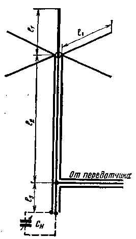
The author tested various types of horizontal and vertical multi-band antennas. The most plausible was the vertical antenna. For a long time operated five band vertical antenna proposed by Y. Medicom (UB5UG). Diagram of the antenna shown in Fig. 1.

Fig.1
This antenna is well described in the literature [1, 2]. The resonant length of the antenna together with the supply line must be equal to 42.5 m, so the length of the radiating unit l1 is determined by the expression (all dimensions in meters) l1=42,5-e(l2+l3), where e is the dielectric constant of a dielectric (for most domestic cable with solid insulation of stabilized polyethylene e=1,51).
Yu Medinet recommends that the length of the radiating portion and balances should be equal to 8.6 m. the Emitter may be formed from a tube with a diameter of 15-20 mm and, if necessary, strengthened by one or two bars of strains. The number of counterweights must be at least four, perform them from a cord or copper wire with a diameter of two to three millimeters. Without any noticeable deterioration of the antenna functioning as a counterweight may be used a metal roof, with sufficient geometric dimensions. Configurable antenna by changing the length of the line segment l3 (on the recommendation of UB5UG l3=2.9 m) minimum SWR in the cable coming from the transmitter, in the range on which you want the most active work. So, when setting up the antenna on the 20-meter band with an SWR less than 1.3, the ranges 10,14 and 40 m SWR can reach 2, 80-meter range - up to 3-4.
Antenna test showed that it works quite well for ranges 10,14 and 20 m, satisfactorily at 40 m (due to the decrease in the length of the radiator) and is not very effective in the range of 80 m (small length and large CWS).
Czechoslovak shortwave M. Checkers (OK1AMS) also uses this antenna [3]. For those cases where the line segment l3 may be placed near the transmitter, he notes the possibility of tuning the antenna on each band by connecting a capacitor (Cm. in Fig. 1). The capacitance of the capacitor does not exceed 450 PF 80-meter range and even less for the other bands. Note that at the connection point of the capacitor is the voltage antinode, so the gap between the plates of the variable capacitor should be at least 1-2mm (depending on transmitter power). In this method of setting the SWR on each band may be no more than 1.5.
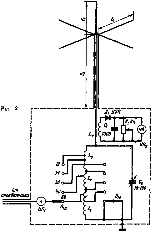
When working in the competition, the conditions of various diplomas successful work on 40 and 80 meter bands is not less important than at higher frequency. In this regard, the antenna was slightly modified (see Fig. 2). Length l1 is increased to 11.2 m, and the length of the supply line is determined by the expression

what cable with e=1,51 is 20.6 m.
Antenna installed on the roof of a small two-story house made of pipes with a diameter of 45 mm, and fortified two tiers of braces. The length of the balances of cord with a diameter of 1.4 mm is the length of the radiator.

Fig.2
Due to the small distance from the antenna to the transmitter application of additional feeder line is not required. The connection of the supply line directly to P-loop transmitter gave good results, but the antenna tuning was difficult due to the fact that when the antenna power is necessary to provide at the point of the antinode of the power voltage, which complicates coordination. In addition, since the antenna is harmonically, in this method, the power, the intensity of radiation of higher order harmonics increases.
To avoid the above undesirable phenomena was made antenna unit constituting an oscillating circuit, enclosed in a screen located near the transmitter. The output of a transmitter using 75 Ohm cable switch PA is connected to a part of a circuit with an input impedance of 75 ohms, enabling the feeder mode traveling wave VSWR on each of the 5 bands close to 1. The inductor circuit, consisting of three series-connected sections L1, L2, L3 switches switch Pb.
The first step in configuring the antenna is to configure the antenna circuit when disconnected from peredatchika the feeder. Using GSS GEAR or with tube voltmeter choose inductance coils for each band in the middle position C2. Coarse tuning of the construction is the selection of turns, precise - changes in the capacitance of the capacitor C2. The second stage settings - selection of points of connection of feeder from the transmitter for each range using the SWR meter any design.
The final adjustment of the antenna is made to the maximum of the readings IP2, loosely associated with the "hot" end of the circuit. As IP used high-frequency ammeter with thermocouple and measuring limit of 3 amps. As IP2 used small-sized magneto-electric device 5 mA. Coil L4-contains 3 turns any wire.
The antenna showed good results when operating on 40, 20, 14 and 10-meter bands. It is especially convenient when working with DX because despite the presence of an additional lobe on the bands 14 and 10 m, the main power is emitted at small angles to the horizon [4]. On an 80-meter band antenna works quite satisfactorily.
The use of the antenna unit significantly reduced the level of radiated harmonics. Careful setup and completely shielding eliminates interference with the TV. Huge advantage is that the antenna tuning is carried out in the workplace. The antenna is grounded but DC and gazobetona.
Literature:
1. "Radio", 1960, N 9, p. 44.
2. Sheiko, V. P., "Antenna Amateur radio", ed. DOSAAF, 1962
3. "Amaterske Radio", 1967, N 2, p. 56.
4. X. Meinke and F. Gundlach, "Radio engineering Handbook" (translated from German), vol. 1, Gosenergoizdat, 1960
Author: Oleg Safiullin (UA4PA); Publication: N. Bolshakov, rf.atnn.ru


