Most often in forest clearings visible variations on a theme dipole "Inverted V" or conventional dipole with two suspension points, for example, between the trees. Well pull the antenna difficult. For field conditions, and in many cases when stationary, it is convenient to install antenna that has two points attachment: one near the transmitter (on the ground, on the window), and the second, for example, a tree or a nearby building. In order to feed a half-wave dipole with one the end, apply a quarter-wave transformer. Once on short waves for this used a quarter-wave symmetric line (antenna "Zeppelin"). Then УSW began to apply a metal Cup or a quarter-wave all-metal two-wire line (J-antenna). Today for LW antenna it is convenient to make the matching device of the coaxial cable.
The author used a half-wave beam vibrator powered it with the end in antinodes voltage using a matching device in the form of a squirrel-cage a quarter-wave coaxial transformer. This design allows positioning a radiant and pithouse-matching part of the antenna on the same line and hang the antenna by pulling at the opposite end through pre - over a block of nylon cord.
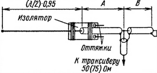
The antenna is schematically shown.

The length of the radiating unit is equal to half the wavelength at the middle of the selected range taking into account the velocity factor (approximately 0,95). This length is in the process of setting up the antenna need not be modified. The estimated total length of the matching line (area a plus area B) equal a quarter wavelength, multiplied by the velocity factor applied cable, which for many brands is equal to approximately 0.66. Cable 50 Ω A=0,214 λk, B=0,036 λk, where λ is the wavelength (m), k is the velocity factor of the cable. For cable 75 Ohm A=0,206 λk,=0,044 λk.
The transceiver can be connected directly to the cable in at some point the distance from the short-circuited end. There is no need to carefully to find a place of connection, the tuner will perform itself the problem of optimal harmonization. If there is a need to connect a coaxial line, and this case, the proposed antenna will facilitate the reconciliation process. Here will also help the fact that the place where the power cord is at some distance from the radiating part of the antenna, being "in the hands" ham, which helps to more closely match the impedance at the point power corresponding to the characteristic impedance of the used feeder.
In urban environments it is sometimes possible to agree on such an antenna leaving the apartment in a comfortable home setting. System setup is selecting a long matching loop and determining the location of the incision for power connection. Greatly facilitates this work the use of coaxial cable with Teflon insulation. It is easy to take, place propela connection on top of the screen braid and without fear of it snapping Central a conductor. It is desirable to use a cable with a characteristic impedance of 50 Ohms, so - as required when configuring devices primarily designed for such a load. Please note, the above formula is valid in that case, if for matching loop and feeder cables used with the same wave resistance.
Precise adjustment of the length of the plume produced by the RF generator and an RF voltmeter, which is connected to the generator output through capacitor of 1 pF. To the exit the generator is connected is short-circuited at the opposite end of period cable. Gradually shortening it, we achieve maximum working voltage frequency.
After clarification of the length of the loop of the transformer make the installation place of the joint cable with antenna. The free end of the cable from the top of the insulation and braid and a distance of about 5 cm firmly tighten nylon fishing line with an insulator from plexiglass. Then to the cable center conductor solder the antenna wire, also pull the insulator by means of a scaffold. The joint is wrapped with a tape and impregnated with BF for the purpose of waterproofing.
To relieve mechanical stress with cable stretch the antenna in the direction source to do with synthetic cord attached at one end to the hole in the insulator, and others, for example, to a peg in the ground. Such prefabricated antenna hang in space at a maximum distance from the conductive items, but so that the matching plume was available for further manipulation with it.
The cable must be cut in the proportions indicated in the figure, to cut received the parts, put them together and re-join by soldering. In the end using the SWR meter must give a small signal power from the transceiver, pre-configuring P-loop or antenna tuner 50 Ohm equivalent. Modifying to some extent the ratio of the lengths of the two pieces of cable, it is necessary to achieve minimum power backward wave. After finishing setting, you should check the reliability of all rations and sealing them.
The working frequency band of the antenna system on a ten-meter range amounted to about 500 kHz, and at forty meters - 120 kHz according to the level of VSWR of 1.5.
Author: S. Makarkin (RX3AKT), Moscow


