Operators of low-frequency bands 160 and 80 meters are constantly striving to improve reception on their stations. The problem is that effective in the transmission antenna (for example, high vertical mast) is collected when you receive too much the interference. The efficiency of the receiving antenna is not critical, since the level and signals, and noise in low-frequency bands is very large and the same is not difficult to apply a low noise transistor the pre amplifier.
Ferrite magnetic antenna is not too good in this respect, though, and has some direction, having two zeros in its radiation pattern (NAM) in the form of lemniscate (similar to "eight"). Ferrite antenna has positioning indoors, where a high level of interference. Made out loop antenna in this respect is somewhat better, but her name is the same, and in the best the case allows only weaken interference from a localized source, giving him zero days.
Truly directional receiving antenna low frequency range is the antenna is a traveling wave (ABC) Beverage representing the wire length in several wavelengths, located low on the ground. However, few Amateurs can afford to build some antennas in length half a kilometer stretched in different directions!
The creation antiamebic directional receiving antennas СLW and LW bands was discussed in the fundamental paper [1]. In particular, it was shown that the combination of the framework and "static" (vertical omnidirectional) antennas gives NAM in the form of a cardioid. Due to the weakening of the reception with some directions there was a significant decrease in the level of interference.
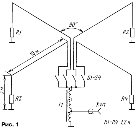
EWE antenna. In this connection, it is of great interest was aroused by the publication about WA2WVL the antenna is called EWE [2]. With its small size and height, it nevertheless have good days, close to the cardioid. In the course of the next year antenna EWE has built many Amateurs, received good reviews, a WB2P suggested the use of four such antennas are combined at the point of supply, for switching days in different directions. In the following publication [3] WA2WVL used this idea by constructing the antenna shown in Fig. 1.

A receiver connected to the antenna 50 Ohm coaxial cable through a matching the transformer T1 with a conversion ratio of 3, therefore, the input the resistance of the feeder from the antenna is increased 9-fold, up to 450 Ohms. Using four relays, normally open contacts which are shown, to the transformer connects one of the four antennas oriented in the desired direction.
Each of the antennas is a rectangle with a height of 3 and a length of 15 m, to one of the vertical sides of which the transformer is connected, and another the resistor. The second terminals of the transformer and the resistor is grounded. The design is very resembles a miniature copy of an antenna Beverage with the only difference that the size the antenna is much smaller than the wavelength. In addition, the maximum reception is from the transformer, instead of the resistor.
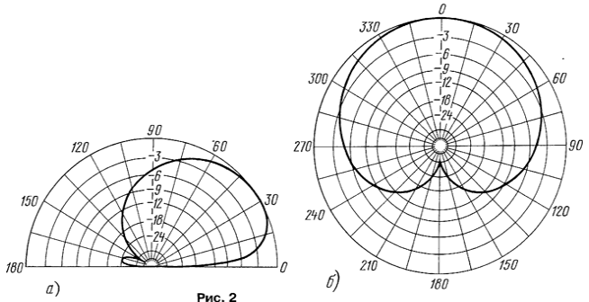
The radiation pattern of the antenna based on the presence of three other disabled antennas, shown in Fig. 2: a - in the vertical plane; b - in the horizontal. This DN is typical of all such antennas, including those described below. Maximum suppression of admission from behind, from the side of the resistor to achieve his exact selection. The resistance of the resistor can vary from 400 Ohms to several of the shortfall. A very broadband antenna, its name and input impedance saved more than fourfold frequency band. To the transmission antenna works poorly because of low efficiency.

In the original antenna was installed on five wooden poles for earthing served a metal pipe driven into the ground at about 1.2 m. the Author argues that due to the high impedance of the antenna earthing resistance practically no influence on her work. The transformer T1 has been wound on the ring with a diameter of about 12.5 mm ferrite magnetic permeability of 850. Winding contained 11 turns of wire folded into three sections. Three of the resulting winding were connected in series, as shown in Fig. 1, and to the first of the taps was connected coaxial connector feeder XW1.
Later the author has built another one the same antenna system is approximately 60 metres from the first, and included them as fairway antenna array, having a a higher coefficient of directional (KND) in the range of 160 meters. Read more on this, see [3].
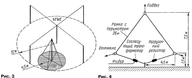
Frame K9AY. Experimenting with directional receiving antennas low frequency Amateur bands and antenna modeling on the computer, Gary Breed (K9AY) offered a very compact design of the two loaded frames, raised on one mast [4]. With the relay installed at the base of the mast, it is possible switch cardioid days in four different directions. Comparative the dimensions of the antenna system of four EWE with the length of the rays by 12 m and framework K9AY it is shown in Fig. 3. Frames themselves have deltabravo form, however, as according to the author, the shape and the dimensions are not too critical. At the base of the mast frame grounded, which provides lightning protection and reduces the noise level. Rod earthing successfully serves as the base of the mast, the very same it is preferable run of insulating material.

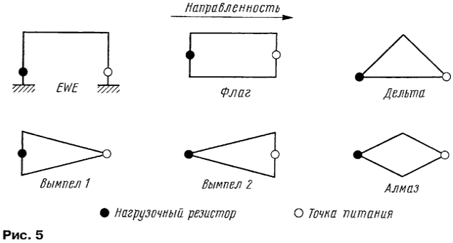
A sketch of one frame shown in Fig. 4, the height of the top point equal to 7.5 m, the side hand drawn by 4.5 m, and the corners are at a height of 1.5 m. it is Possible, as shown in the figure, to do entirely without masts, suspending the upper point antenna system for a branch of a tree, for example, using the ropes. In the corners of the frame it is convenient to use Marinova insulators with holes. The lower ends of the wires framework drawn to the ground rod also using Marinova insulators, remaining after binding of the ends of the wires insulators sent to waterproof box with relays and a matching transformer, such described above.
Explaining the operating principle of the antenna, the author notes its similarity with the directional taps, a widely used technique in RF and microwave, in particular, in the SWR meter. If EWE antenna is polarama, reverse the wire which is the ground, the K9AY loop is full frame, but the principle the actions are very similar. Antenna responsive to both the electric E and magnetic H component of the incoming electromagnetic field.
For electric field components of the antenna behave as short vertical, creating a voltage at the connection point of the feeder. As you might expect from the vertical antenna, the NAM field E is obtained omnidirectional.
This is not the case with the magnetic component of the field H: crossing the plane of the antenna, she is a current circulating around the perimeter of the frame. This current passing through a load resistor creates a voltage, which is formed with voltage from field E. If the wave comes from the connection points of the feeder, both voltages are added. If the wave comes from the load resistor, voltage subtracted, since the direction of the field H, penetrating the frame is reversed.
Changing the load resistance, it is possible to balance both voltage so that they were equal. NAM in this case takes the form cardioid with a single zero. The weakening of the signals coming from the the load resistor may exceed 40 dB, which is more than 6 S-units on a scale of signal strength!
Zero days is not in the plane of the earth, and how the computer shows modeling, elevated at an angle of from 20 to 55° depending on configuration antenna and properties of soil. Short and high loop gives zero angle NAM elevation 30 to 40°. This helps to reduce QRM from local stations.
Essential and necessary part of the K9AY antenna is grounded. In depending on the parameters of the soil may need a little adjustment, the resistance of the terminating resistor. The land need not have losses, as in the case of the antenna of Beverage. The frame has the focus, even over a perfectly conducting earth. This means that the antenna operates at almost any parameters of the soil.
In the comments that followed the publication of the article [3], W6FA reported that the ancestor of all loaded loop antennas should be considered the same Harold Beveridge who patented a similar antenna in 1938, much later than its the famous "wave antennas", or, as it is now called, the antenna is a traveling wave. In the patent of Beverage described a complete loop antenna that does not require the land for their work and having a load resistor of about 700 Ohms, placed at a point opposite the feed point. This broadband antenna even then supposed to be used for television reception
Antenna Flag, Pennant, etc. Intensive modeling of antennas with radio Amateurs the use of computer programs has led to the emergence of a number of antennas [5], similar to that described. Antennas are triangular, square, rectangular or rhombic frame, located in a vertical plane. The possible configurations of these loop antenna shown in Fig. 5. Bright circle indicates the source (receiver), the dark circle - load resistor an impedance of 400 Ohms and higher, typically about 900 Ohms. About the same is obtained and the input impedance of the antenna. Directivity - cardioid, the direction of the reception - side source.

For operation in the 160 meter band antenna type Flag, both Pennant (Pennant) and Diamond (Diamond) have a size of 4.3 in height and 8.8 m in length. Antenna Delta (Delta) has a height of 5.2 and a length of 8.4 m
Compared with EWE and K9AY loop these antennas offer significant difference they do not require grounding, although there are comparatively low, at the height of about 2 m above the ground. Reducing a height of 0.3 m almost little affects the antenna characteristics.
The antennas were made in different versions and with different sizes, for example, JF1DMQ reduced the size to 1 X5 m Antennas work well also in the ranges 80 and 40 meters. Especially the hams noted a low noise level of these antennas.
As an example, consider the triangular "Delta", used FO0AAA for admission in the range of 160 m [6]. The bottom horizontal wire had a length 8,54 m and located at a height of 0.9 m above the ground. The height of the triangular frame was 5.2 meters, measured from the bottom wire (6.1 m from the ground). All it took about 22 m wire diameter of 1.63 mm In the lower corners of the frame were included a load resistor 950 Ohms and a power transformer, converts a resistance of 50 Ohm feeder 950 Ohms.
At a frequency of 1830 kHz the radiation back/forward was better than 40 dB, while the gain of the antenna compared to an isotropic radiator was just -34,5 dB, which means lower efficiency and the need to use low-noise pre-amplifier in conjunction with this antenna.
The frame was mounted on a dielectric mast, the lower ends of the "Delta" stretched on the pegs of the tents. Orient the antenna is very simple: a permutation of the pegs.
Finishing the review, we can state that there is a ham radio there is a new class of foster directional broadband antenna with low the level of noise and small size.
Literature


