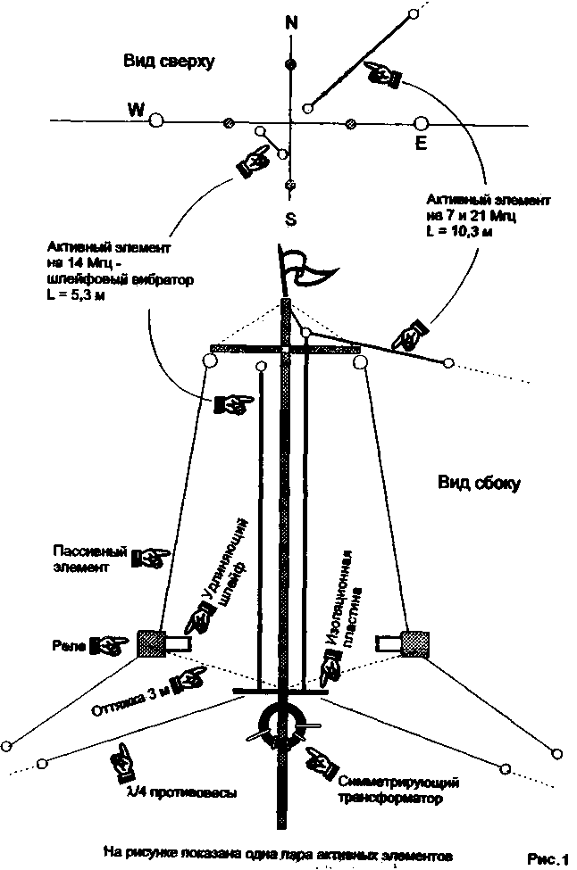
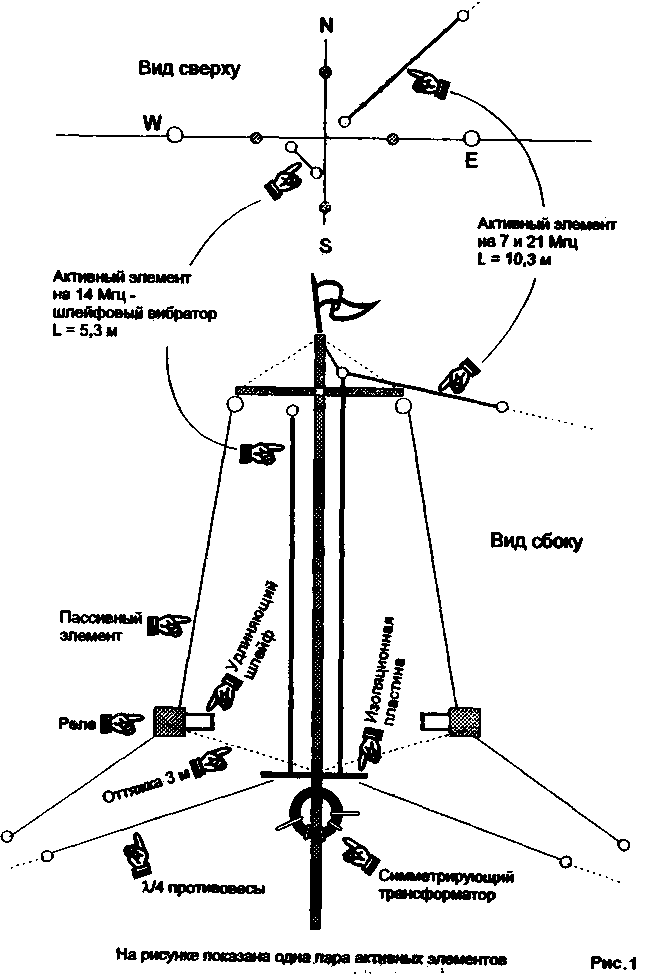
Based on the design of the vertical antenna from the book of K. Rothammel, but instead of a vertical half-wave dipole with the aim of increasing the wave resistance is used Daisy emitter with a system of counterweights at an angle of 120 degrees. Four passive antenna element are bent at the same angle. In the middle of each passive element mounted relay, Fig.1.

It is known that the maximum radiation of the antenna falls on a location where there is high current. If the mounting height (suspension) of the antenna is less than 1/4 lambda, it is better to use a vertical arrangement of the radiator (vertical polarization). Designing this antenna, based on the following prerequisites. While staying in a block of 5-storey building, the roof of which is public by definition, something not wanted to use expensive materials and components - very risky - rested. So there was a desire to minimize the cost of its production. The proposed antenna for the 20 meter band does not contain scarce materials and covers an area of 10 by 10 meters, works, in my opinion, HC worse than the double of a square, and a switching time of the radiation diagram in under a second.
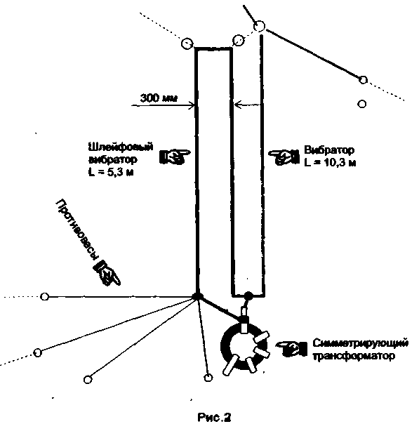
The basic structure is a metal (steel) pipe diameter of 25 mm and a height of 9 meters with a metal cross on the top. The length of each beam of 2.6 meters (1.3 m in each direction). Below at a distance of 5.5 m is mounted an insulating plate on which are mounted counterweights and Daisy vibrator, stretched parallel to the pipe mast. The distance between the active and passive elements at the top and bottom is not critical and is selected 1 ... 1.5 m. the Distance from the point of supply to the relay is equal to 3 m and is determined by the length of the guy wire between the relay and the insulation plate. The crossbar is welded at 0.5 m below the upper end of the pipe and escalivada steel wire. The lower ends of the passive elements and balances through short delays are fixed on the roof and how-to amplify the antenna, so it is enough of one tier of guys going from 1/3 of the pipe above. The length of the Daisy chain VIB-ATOR about 5.3 m, and the distance between the wires 30 cm Length balances 5.3 m, Fig.2.


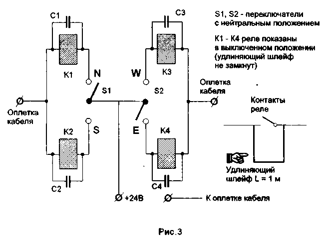
The length of the passive element as Director - yum, the relay contacts close lengthening the loop. The length of the passive element as a reflector 11, the relay contacts are open. Wire cable length 1 m suspended on a sling that goes from the relay. The switching relay type RES-9, the two groups of contacts are connected in parallel. Parallel to the windings of the relays installed capacitors of 0.01 µf Fig.3.
The radiation of the antenna (radiation pattern) switches two switches with a neutral position. One switches the direction East-West, the other North - South. Each position of the switch connects the corresponding relay.
The possible eight (8) business combinations:, 4 positions - one Director, three reflector and 4 positions - two Directors giving reflector, which corresponds to the choice of the following directions: North, North-East, East, Southeast, South, southwest, West, Northwest.
The power antenna is a coaxial cable of 50 Ohms. Balancing and noise reduction when taking this same cable on a ferrite ring with a magnetic permeability (600 - 2000 NN) is wound 5 ... 10 turns. The ring is in close proximity to the feed point of the antenna.

The antenna tuning is to set the length of the vibrator on low VSWR, and the selection of the length of the reflector necessary to achieve maximum suppression ago. Make it very convenient, since the end of the reflector is low on the roof.
Estimated correspondents when compared with the dipole win is two points, and the suppression of the posterior lobe comes to four.
Without much deterioration of the antenna parameters can be made in three bands, and implemented in the final version. Parallel to the pipe mast (not shown) from the feed point to the top of the pipe, and then sling to the side is the wire length of 10.3 m (at a frequency of 14 MHz it has a high input impedance and does not affect the main antenna). Connect the same length counterweights and the antenna starts to work in the range of 7 MHz, as shortened GP, as well as on the 21 MHz band at the third harmonic. The number of counterweights on each band must be NS less than four. It is also noticed that the antenna works quite well even in the range of 28 MHz.
At the fundamental frequency antenna has a small emission angles in the vertical plane and it is highly effective at carrying out long-haul communication. On short routes (distances) sometimes loses "rope" antennas.
Author: V. Tsitko, RW4CB, G. Rtishchevo; Publication: N. Bolshakov, rf.atnn.ru


