The figure shows the design of the triangular antenna (Delta-Loop) for the range of 10.1 MHz.
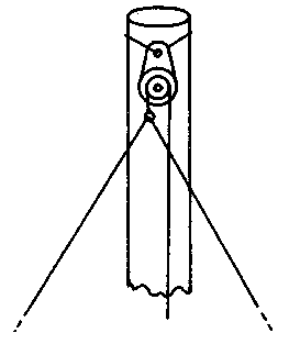
Fig.1
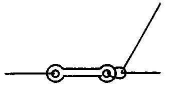
Fig.2
Delta gave increment gain on average by 6 dB in comparative tests with conventional dipole "Slapper" during the QSO's ten stations of Germany. In Fig.1 shows the top of the mast with lifting roller and the upper corner of the canvas antenna, Fig.2 - mount the bottom corner of the canvas through the insulator to the stretching of synthetic rope, Fig.3 - scheme of gamma-ray Aligner, Fig.4 is a sketch of a Delta-Loop.
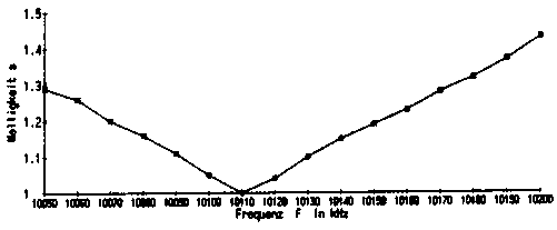
Fig.3

Fig.4
In Fig.5 shows the structure of the closing jumper Aligner, Fig.6 - frequency dependence of the CWS.
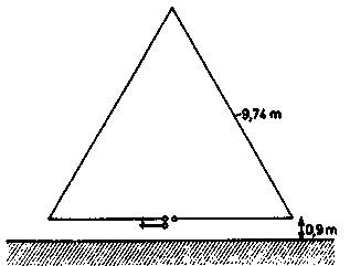
Fig.5
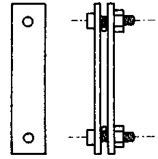
Fig.6
Literature
Publication: N. Bolshakov, rf.atnn.ru


