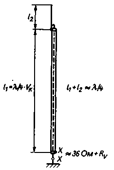
The so-called antenna Groundplane type with built-in short-circuited quarter-wavelength loop of coaxial cable (Fig.1). The main advantage of antennas of this type - extended frequency range.

Fig.1. Scheme coaxial vertical antenna (Rv - amount of resistance losses)
It is formed by a vertically disposed coaxial cable with arbitrary impedance. The lower end of the Central cable conductor connected to the grounding network, and its upper end soldered to the shield of the cable. The cable length l is equal to l/4хVk, where Vk is the value of the velocity factor of the specifications (usually 0,66). Thus, we are talking about closed coaxial quarter-wave line, serving as a parallel resonant circuit. Radio waves are emitted only by the shield of the cable, but due to the low l/d ratio of its velocity factor close to 0,95, and because he's too short for quarter-wave resonance. To form a quarter-wave Ground-plane, requires l1 to increase the length l2 to the resonant length l/4.
Example
Use a coaxial cable Vk=0,66. Geometric quarter wavelength l1=0,25lх0,66=0,165 l. If the shield of the cable to take into account its l/d ratio of the velocity factor V=0,95, the normal length will be l1+l2=0,25lх0,95=0,2376 l, and the length of the line segment l2=0,2376 l-0,165 l=of 0.0725 l. At resonance the integrated quarter-wave loop not working because of the very high input impedance (parallel resonant circuit). If you raise the frequency of the transmitter, the line segment l1+l2 is too long - in other words, it appears inductive reactive component. At the same time becomes excessively long and short-circuited quarter-wave coaxial line (loop). Line, surpassing a quarter wavelength, has a capacitive effect, and as a result of the inductive component of the line segment of the radiator and the capacitive reactance of a quarter-wave loop are mutually compensated, and radiation resistance Rs increases.
With decreasing frequency the transmitter is reversed: the portion of the emitter becomes capacitive and the plume - inductive, which also leads to mutual compensation of reactive components. Due to this ability of a quarter wave line frequency band of the antenna extends. At the top of its limit unwanted change the directivity and the bottom is a sharp drop in the radiation resistance. Due to the high bandwidth such the length of the antenna elements is not necessarily accurate to withstand. As for the other vertical antennas, solid grounding network is a prerequisite for high efficiency.
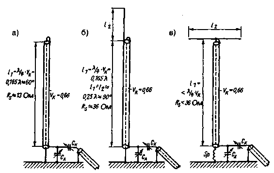
DL2FA described coaxial antenna [1]. Sketch the simplest of them is shown in Fig.2A.

Fig. 2. Types of vertical coaxial antennas:
a - shortened Groundplane; b - full Groundplane;
in a very short Groundplane with a lengthening coil L and the terminal capacity CD
If the velocity factor of the coaxial cable Vk=0,66, its geometric length will be 0,25lх0,66=0,165 l; it is the length of the radiator, because no means of elongation of this element was not used. Therefore, there is a shortened Groundplane length ~60° (1 l=360°). The radiation resistance Rs of this version of the antenna is approximately 13 Ohms. To achieve high efficiency antenna resistance losses should be the lower, the lower the radiation resistance. Somewhat more favorable conditions creates the use of coaxial cable with airy dielectric and Vk=0,82. Then the cable length l1=0,25lх0,82=0,205 l (about 74°), the value of the radiation resistance (20 Ohms). Thanks already described the action of the quarter-wave coaxial loop input impedance remains active in a wide range of frequencies, and its magnitude varies with the radiation resistance. With the help of omega-matching network (SA-SC) are consistent with a characteristic impedance of any cable.
Fig.2B corresponds in principle to Fig.1, differing only in the display of the antenna parameters and omega-length negotiation. In Fig.2B shows a much shortened Groundplane with a lengthening coil and terminal capacity.
Coaxial antennas are operated in multi-band mode. In this case, you should be aware of changes in the vertical directional diagram with the transition from one band to another and radiation resistance, and the need for adjustment of the omega-shaped element when switching bands. This is not required when working in a single range.
Significant frequency bandwidth opens up many possibilities of adjustment to the local conditions. Coaxial cable needs to be artificial or natural support. The ideal solution would be a fiberglass tube with coaxial cable inside. Sometimes you can run a cable between two high-mounted anchor points (e.g. trees).
Literature
1. Wurtz H. DX wireless antennas mit spiegelnden Flachen - Koakxiale wireless antennas. cq-DL 7/1981, S. 330-332
Publication: N. Bolshakov, rf.atnn.ru


