One of the reasons that determined the marked increase in the activity of the Soviet Amateurs and their successes in international competitions, is the widespread use of directional antennas. The most popular in our country steel "squares" with two, three or more elements of the beamforming. These antennas will be discussed in the article. The main objective pursued by the authors, is to give recommendations to the shortwave in choosing and setting up antennas, generalizing the experience of Soviet and foreign Amateurs.
Comparison of "squares" and "wave channels"
The wide distribution of "squares" has led to the need to compare their features with other popular ham radio antenna - "wave channel".
The table shows the results of measurements of some characteristics of antennas "square" and "wave channel", taken from the magazine "QST", 1968, No. 5. It follows from this. what are the parameters of the two antennas are about the same, if you compare "wave channel", which has one element larger than "squares". At the same same number of elements "square" will be increased by approximately 2 dB more. According to our records this number can be increased at least up to 2.5 dB, if you select an optimal distance between the elements.
Antenna settings Square Wave channel
The number of elements
2
4
6
3
5
7
The gain relative to
isotropic radiator, dB
8.2
11,5
13,4
8.8
12
13,3
Beam width
the half-power level, grad.
60
50
39
61
47
40
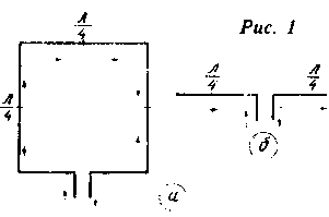
To understand the physical cause such a significant difference, consider the directions of the currents (Fig. 1) in a frame member of the "square" and in the half-wave dipole element "wave channel".

From Fig. 1 shows that in the formation of the diagram of the "square" involved only the currents flowing in the horizontal parts of the frame, as fields from currents flowing in the vertical parts cancel each other out. Therefore, a frame is equivalent to the system of two-phase excited by short vibrators, spaced in height at a distance of L/4. It is known that the radiation pattern in the vertical plane of such a system compared to the diagram of a single dipole has a smaller angle and therefore its gain is higher. Quantitatively the gain in the amplification depending on the parameters and elevation of both elements can range from 2.2 to 3.1 dB. This gain can be determined by the formula, just with sufficient accuracy for LW ranges:
A=40000/Fllv where A is the amplification factor, FG and VWF-width of the radiation patterns in the horizontal and vertical planes respectively.
Substituting in the formula the average values FY=180° and PV=135°for a dipole FY=170° and EF=80° for the frame, get the gain of a dipole is equal to 1.64 times or 2,15 dB (power), increased frame - 2.94 times or to 4.68 dB. Thus, the average gain in amplification is 2.53 dB. This figure is real and confirmed in practice.
A similar winning is achieved at the location of the frame downward angle used in many designs. This option differs from parsed above only in that the directional diagram form the horizontal components of the currents flowing in all four sides of the frame, and the fields from the vertical components are compensated.
It is possible to note one more feature of the "square". Since the frame length L forms a symmetrical closed loop, the influence of the ground and surrounding objects, deteriorating the characteristics of the antennas is lower.
The choice of optimal design Under optimal we understand structural data such antennas, which provide a maximum ratio of radiation forward/backward at high gain. To enter this definition is necessary because of the existence of two methods of setting directional antennas for maximum gain and maximum ratio of radiation. These maxima do not coincide, and, as practice shows, the loss in respect of radiation forward/backward when it is configured as the first technique is greater than the loss in gain in the second case.
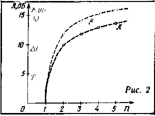
In the process of designing the antenna Amateur radio operator should determine the number of elements, the distance between them and their dimensions. To solve the first problem, refer to Fig. 2.

It shows the dependence of the antenna gain and the ratio of the radiation forward/backward In the number of elements n. Graphs are constructed based on the measurement results (coincident with the calculated data) on the antennas "square" with optimal characteristics for the 14 MHz band. As you can see, the increase of both parameters with increasing number of elements is slowing, and this becomes especially noticeable when n>3. Given the difficulties associated with the manufacture and setting up of multi-element antennas, the authors believe that in most cases it is advisable to limit the number of items to three. In the opinion of some foreign radio Amateurs structurally more convenient up to the antenna due to the symmetric (about the vertical axis passing through the center of mass) of the elements. The ultimate solution we provide to readers.
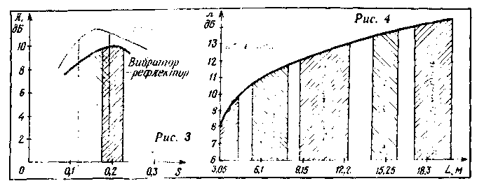
To select the optimum distance between the elements let us consider the dependence of the gain And the distance S, expressed in fractions of the wavelength L (Fig. 3). On the chart black color shows the dependence of the gain on the distance vibrator - two-piece reflector the "square". In the shaded region corresponding to the maximum gain (S=0,175-0,225 L), it does not change, so in this case, the choice of the distance within the specified limits are not critical.
For antennas with the number of more than two elements, the task is complicated due to the introduction of an additional independent variables (three-element antenna - two, up three, etc.). It is therefore advisable to ask one of the distances (for example, between the vibrator and the reflector) and choose the optimal distance. So, if taken for three-element antenna distance vibrator - reflector equal to 0.2 L, we can determine the optimal distance vibrator - Director, using the curve shown in Fig. 3. Obviously, the largest increase this "square" will be at a distance vibrator - Director, equal 0,175 L, and in this case, when changing distances from 0.14 to 0.21 L Wuxi-tion remains almost constant, although, as expected, due to the reduction of widely polosnost antenna dependence of the gain on S becomes steeper.

To illustrate this, you can give some converted to "squares" on schedule 14 MHz from the journal "QST". Based on the study of a large number of antennas was determined the dependence of the gain on the beam length L of the fastening elements (Fig. 4). The shaded region on the graph is practically possible change limits the length of the beam antenna with a given number of elements. It follows from the graph that the antenna with a short traverse inferior in amplification (two - and three-piece - about 2 dB) antennas, with the distance between elements about 0.2 L.
The length of the vibrator frame l can be calculated by the formula:

where Ky is the coefficient of elongation, depending on the number of elements and relationships the length of the frame to the wire diameter; Lр-wavelength, which is calculated antenna.
To determine the length of the vibrator element of the "square" elongation is taken equal to 1.01, at three or more elements it is equal to 1.015-1.02.
The length of the reflector element of the "square" choose 5-6% greater than the length of the vibrator. For three-element the "square" is the length of the reflector should be 3-4% more Director - 2.5-3% less than the length of the vibrator; for up to the "square" is the length of the reflector should be 2.5-3% more lengths of Directors - 2% less.
Almost the reflector and Director are made somewhat shorter than those determined by calculation, using a short-circuited loops you can configure.
Mnogotirazhnye system
Everything said previously belonged to a single "squares". In practice, however, often have to resort to the creation of a multi-band systems. It should be noted, however, that any combination in a vertical plane elements tuned to different frequencies, especially multiples of two (14 and 28, 7 and 14 MHz, etc.), resulting in deterioration of the main characteristics of the antenna. Here are two examples. Two-element "square" on 14, 21 and 28 MHz with frames in different planes (the so-called design "hedgehog") has a gain of up to 9 dB and the ratio of the radiation forward/back - to 24 dB; the same characteristics similar the "square", performed at the traverse, do not exceed 8 and 22 dB, respectively. Three-element "square" on two ranges (14 and 21 MHz) with spaced reflectors provides a gain of up to 13 dB and the ratio of the radiation forward/backward up to 30 dB; the three-element triband the "square" (added 28 MHz and frames are arranged one inside the other), these properties will be reduced accordingly to 11.5 and 27 dB.
To reduce the influence of elements arranged in one plane and operating on multiple frequencies, it is possible, appropriately connecting the feeder to apply their polarization isolation (horizontal polarization and vertical for the other bands).
Certain by calculation, the denouement of the elements ranges 14-28 MHz in the three-element "the square" is 20 dB.
To get the best performance multi-band systems, it is desirable to maintain an optimal distance between the elements for each band. Here, however, because of the structural difficulties ham radio operators are often forced to compromise. One example of such a compromise for three-element the "square" on 14, 21 and 28 MHz can be to achieve close to optimal performance on the first two bands and the worst - in the third. In our opinion, such a decision is justified due to the nature of the transmission and different load these ranges. Depending on specific requirements to the antenna Amateur radio operator may choose another option.
Literature
Publication: www.cxem.net


