


")

We offer our readers a description of the design of the antenna operating on all Amateur bands.
In the survey Three LW antenna" ("Radio", 2000, No. 4, pp. 62-64) it was noted that the T2FD antenna type, containing in the fabric of the emitter resistors, can be used at frequencies below and above the optimum, for which they are designed. In Amateur radio magazines and on the Internet recently appeared advertising the antenna D2T. It claims its manufacturer - firm WiMo, operates in the frequency range from 1.5 to 200 MHz. Since the antenna is manufactured, it has been studied well enough. The results of these studies are of interest to all who have decided to make the antenna with a resistor in the fabric of the radiator.
Antenna D2T (Andreas Splanemann, "D2T - alle Bander mit einer Antenne?", 2000, No. 2, S. 116-119) is a two loop vibrator, spaced horizontally from the active power and the resistor in the fabric of one of them (Fig. 1). Loop vibrators have a length of 6 m, and the distance between the sides of a loop of about 0.15 m. the distance between the vibrators - 2 m antenna Power is supplied via a coaxial cable with a characteristic impedance of 50 Ohms through a matching-balun transformer with a transformation ratio of the resistance 1:9. Load resistance - 820 Ohms.
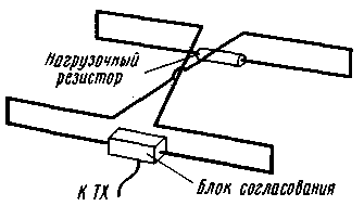
Fig.1
According to the manufacturer CWS within all Amateur LW bands and on the 144 MHz band does not exceed 2. Hams, reproducing this antenna, and got different results on the CWS. Almost all of it really was mostly less than 2 and only in selected hams on some Amateur bands the SWR was lying in the range 2…3. Discrepancies with the company can be attributed to local conditions (for example, by not giving in to the account of influence surrounding the antenna hardware).
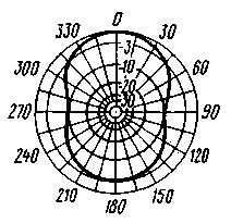
Fig.2
The directivity for the antenna D2T in horizontal and vertical planes (range 14 MHz) is shown in Fig. 2 and 3, respectively. At this range (as in other high-frequency LW bands) radiation pattern in the horizontal plane has a certain targeted properties. The ratio of the radiation back/forward, however, is small (a few decibels), but the ratio of the radiation forward/sideways reaches 10 dB or more. The latter allows you to use D2T at these ranges as a rotating directional antenna (for noise reduction). On the 14 MHz band D2T in the direction of maximum radiation is slightly inferior to the dipole (-1 dB), and in the range of 28 MHz it significantly outperforms (+6dB).
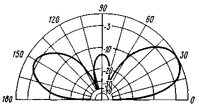
Fig.3
In the lower frequency ranges (7 MHz and below) the antenna pattern in the horizontal plane is almost circular, and the vertical maximum radiation begins to shift to the Zenith. On the 7 MHz D2T inferior to the dipole 6.5 dB, taking into account the size of the antenna can be considered as an acceptable value.
On the 144 MHz band, the antenna pattern resembles a "Daisy" with a few dips to 10…15 dB relative to the maximum emission.
Fig.4
The antenna design D2T simple. It consists of a supporting cross member (BOOM) 2 m in length, the ends of which is fixed to the dielectric tube length 3 m (Fig. 4). They are the basis for the wire loops forming the emitter. To support the upper portions of the loops each element has three dielectric stand - one in the center (Fig. 4) and one at the end of each dielectric tube (Fig. 5). These pipes and to vertical racks wire cloth antenna is attached with a strap of adhesive tape.
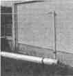
Fig.5
Central rack are in the upper portion of the dielectric cross-beams with a length of about 0.1 m (Fig. 6) that secure the wires forming the top of the emitters, and wire line connecting loop vibrators.
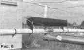
Fig.6
Matching balun transformer housed in a waterproof casing, which is mounted on the carrier traverse (see Fig. 4). A resistor is placed in the interval of the dielectric tube length of 0.3 m and mounted on the dielectric tubes that support the lower wire of the corresponding loop (Fig. 6). According to the firm in the "Press" for different frequency bands to the antenna can sum up the following power: 100 W to 1.5…2.5 MHz, 200 W - 2,5…4 MHz, 400 W - 4…10 MHz, 500 W - 10…30 MHz, 200 W - УSW ranges. Since at low frequencies most of the power supplied to the antenna is dissipated in this resistor, we can assume that the load resistor must have a power dissipation of 100 watts.
It should be noted that the ratio of power dissipation of the resistor and the power capability of the transmitter in the main working frequency band for the antenna D2T is about 0.2. This parameter is she better than T2FD for which it is usually recommended to choose approximately 0.3.
Author: Andreas Splanemann; Publication: N. Bolshakov, rf.atnn.ru