


")

The article presents several designs of popular j-antenna. As you know, this is a half-wave radiator, end-fed with the help of a short-circuited quarter-wave line.
In Fig.1 shows the antenna on 2 meters, where the emitter diameter 6 mm length 1 m is connected at the bottom with a piece of matching length of 50 cm and a diameter of 8 mm At a distance of 5 mm from this segment is the second segment of the matching length of 50 cm and a diameter of 2 mm, 50 ω power cable is connected at a distance of 2.5 cm from the bottom, as shown in Fig.1.
Fig.1
The same antenna on 70 cm consists of a radiator with a diameter of 4 mm length of 30.8 cm, matching the length of 15.3 cm (its left conductor made of the same rod as the emitter and the right of rod with a diameter of 2 mm at a distance of 8 mm), power point 1.3 cm from the bottom. Matching line can be made of coaxial cable.
Fig.2
In Fig.2 shows this option to 2 m or 70 cm, the total length of the line is a quarter wave taking into account the velocity factor of 0.68 for RG213 cable and the power cable is connected at a distance of 5% of the entire length of the line measured from the lower end where the cable connects to the Central core.
Fig.3
The same line can be used for short-wave dipoles (Fig.3), where the size and In are listed in table.1.
Table 1
Range, MHz
S, m
In, m
28,5
1,501
of 0.236
27,25
1,569
0,247
24,96
1,713
0,27
21,225
2,015
0,317
18,14
2,358
0,371
14,175
3,017
0,475
10,125
4,224
0,665
7,05
6,066
of 0.955
3,65
11,717
1,844
1,834
of 23.32
3,671
A sketch of such an antenna for 10 meters is shown in Fig.4, and the dependence of VSWR against frequency in Fig.5 (the upper curve is calculated, lower the practical effect).
Fig.4 - 5. An interesting variant of the antenna is a dipole of coaxial cable type RG213 or RG58U depending on the operating frequency (Fig. 6).
Fig.6
In the dipole does not need additional balancing or alignment. Due to the design features of the antenna has an impedance of about 50 Ohms. The desired resonant frequency is produced exclusively by lengthening or shortening La shoulders. As an example of the calculation for 70 cm from RG213 cable: L1=140,8/f[MHz], L2=99,4/f[MHz] here are already taken into account the velocity factor. For 423 MHz L1=0,326 m and L2=0.23 m and La=0,048 m From the midpoint of the cable length of 32.6 cm left and right remove 5 mm external insulation, and one in the middle is removed over a length of 8 mm, leaving 1 mm, which gently ludyatsya, they are points of connection of the power supply (Fig.7).
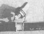
Fig.7
From the outer ends towards the middle of the external insulation is removed over a length of 48 mm, and a screen braid is removed so that was still visible 3-4 mm of the core Insulation is also removed over a length of 48 mm. Then the remaining 3-4 mm screen folded onto the Central conductor and soldered. As can be seen from Fig.8, the coaxial dipole without problems can be used as an emitter for Yaga.
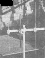
Fig.8.
Author: günther Grunbeck, DH1NAW; Publication: N. Bolshakov, rf.atnn.ru