


")

In the manufacture of GP on low frequency ranges are usually Amateurs forced to choose between efficiency of the antenna and its size. Because the current GP height range of 80 meters (about 13 m, we should expect that by judicious use of "lengthening" of the elements of the antenna of this length will be quite effective. To set short antenna into resonance can end capacitive load and/or inductor.
The capacitive load is usually performed in the form of several conductors located perpendicular to the fabric of the radiator and is located at apex. This kind adaptability ensures maximum efficiency of the antenna I. therefore, is the priority. From design considerations the length of the conductors are choosing not more than 0,03 l, which limits the possibilities of this method.
The use of inductors is less desirable, as it significantly reduces the efficiency of the antenna as a whole and her band of operating frequencies. However, for the effective shortening of the antenna, in practice, often use both. Loss in the coil can be reduced, if you do it in one or two turns sufficiently large diameter. Although such inductors are more difficult to the manufacture, they provide more bandwidth (when the diameter of the coil about 0.01 and it works partially as emitter).
The advantage of this design is in the fact that the coil makes a certain capacity relative to the ground, which further shortens the antenna.
The combination of these two methods and used in antenna for 80 meters band (Fig. 1).
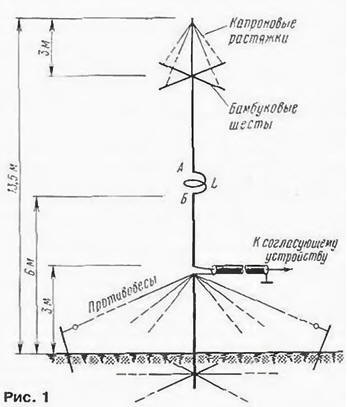
The base of the antenna is a metal pipe which extends above the surface land at 3 p.m. In the lower part attached to the base of the five radial divergent and in-depth 10 cm into the soil grounding wires with a length of 25 m. The ground wire is made of galvanized steel wire. In the upper part connected to the base of six radiating balances in length 19 M.
On the basis of fixed (through the insulator) emitter height of 10.5 m. consisting of two pieces of metal pipe length of 3 m (bottom) and 7.5 m (top). Segments the emitter is mechanically coupled to each other through an insulating bushing with the cross, which is a coil of inductance L.
The design of the inductor L shown in Fig. 2.
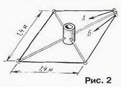
Insulating sleeve fixed four bamboo sticks with a length of 1 m. At the ends of the sticks installed porcelain roller insulators, and on one of the sticks of these two insulators. Coil, made from antenna cord with a diameter of 5 mm. secured to these the insulators and their ends connected to the upper and lower parts of the radiator Capacitive load at the top of the radiator is made of four electrically connecting the segments of the antenna cord length 2.5 m and a diameter of 3…5 mm. stretched along the bamboo poles (fishing rods). These poles are not bend, they are supported by nylon cords.
The radiator in position hold two tiers of nylon stretch marks (on four in each).
Feed the antenna 75-Ohm coaxial cable length of 12 meters Between the cable and transceiver included matching device (see "Spiral" GP for bass ranges" in the "Radio", 2000, No. 1, p. 64).
The antenna showed good form when running on ultra long-haul routes, providing communication from all continents.
Author: E. Osmerkin (UA4ANV)