Due to the rapid increase in the number of television broadcasting channels is very difficult to provide high quality reception of all TV programs. First of all, it depends used antennas. Therefore, below we consider their basic designs, tested by the author in various conditions. But first let us recall basic information about TV frequency ranges and channels.
Television cover the frequency interval 48,5...790 MHz. They are divided into meter (channels 1-12, frequency of 48.5...230 MHz) and UHF (channels 21-60, frequency 470...790 MHz) ranges. One television channel occupies a bandwidth frequency 8 MHz. To calculate the operating wavelength of the antenna, it is recommended to choose the carrier frequency of the image as an image signal amplitude-modulated, is more susceptible to interference and requires more gain than the frequency-modulated sound signal.
The carrier frequency of the image for the 1st and 2nd TV channels equal and 49,75 59,25 MHz, respectively. For 3-5-th channels (in megahertz) is calculated as: FH.from=77.25-meter+(N-3)x8, where N is the channel number; for 6-12th: FH.from=175,25+(N-6)x8, and for 21-60 th: Fn.from=471,25+(N-21)x8
The mean frequency of the channel strip can be obtained by adding to the value carrier image the number of 2.75. The carrier frequency sound above the frequency carrier image at 6.5 MHz. The working wavelength L (in meters) in the air in depending on the operating frequency f (in megahertz) is determined by the formula l=300/f. In other dielectrics wavelength less (for example, polyethylene 1.52 times). This fact must be taken into account in the manufacture of resonant elements matching devices from polyethylene coaxial cable.
Now, some of the constructive execution of the antennas. Material for them the manufacture it is desirable to use tubes, rods, strips, angles, wires from metals and alloys with good electrical conductivity (copper, aluminum, brass). From the surface area of the active elements depends on the broadband antennas: the more area (larger the diameter of the tube or the width of the strips), shirokopolosnoe will the antenna (but also heavier). It is not recommended to choose the transverse dimension elements (tubes, rods) of the antenna is less than 1/200 of the wavelength on which it works, as this significantly deteriorate the electrical parameters and the mechanical strength. The width of the strips is chosen in 1,5...2 times the recommended diameter of the tubes or rods, a thickness of 2...3 mm.
The surface must be flat and smooth. For best UHF range results are obtained if applied elements from a material with polished surface, because the RF currents are induced only in their surface layer. If you want to bend the antenna elements, do it gently, placing a sponge the grip pieces of PCB or wood, so as not to damage the surface. Tube before that should be tightly filled with sand and plugged with wooden plugs.
When installing the antenna outside of the action of lightning rods make them reliable the lightning protection [1]. In addition, you should carefully sealing electrical the connection and the place of exit of the wire from an external insulation, the Gulf water and heat-resistant dielectric varnishes or resins.
For accurate orientation of the antenna to the desired direction of the signal at the input of the TV should be loosened several times attenuator. When it ceases to act AGC system of the TV and become more noticeable accept a maximum of signal.
And finally, about the antennas. Let's start with narrowband. They are designed to receive any one of a television channel or more, provided that their frequencies differ by no more than 5...10 %. In this case, the antenna count for compound frequency, calculated as the square root of the product of the frequencies of each channel, or the frequency of the signal of the weaker channel.
The antenna also divided into the simple and complicated [2]. Last may contain but one active element, reflector, Directors and even additional active elements.
The simplest antennas are equally welcome as the direct signal and the signal coming from the opposite direction from the telecentre direction. They have the low gain (and directivity). Therefore, their use is usually limited a small distance from the transmitting antenna in the absence of the reflected signals (visually they appear on the TV screen in the form of megacontract or image blur).
The simplest antennas is linear split half-wave vibrator" [1, 2], depicted schematically in Fig. 1. It has an input impedance on resonance frequency of about 75 Ohms. It is strengthening its usually conditionally mistaken for 0 dB. The vibrator is made from tubes, rods or strips. The diameter d of the tubes chosen equal to 20 MV 30...and for UHF - 6...12 mm. the distance between the ends tubes l must be equal to half the operating wavelength of the antenna, multiplied by the velocity factor depending on the ratio of the diameter of the tubes to the working length wave. For the relationship of 0.001 and 0.003 values of the coefficient of 0.96 and 0.95 respectively. If it increases to 0.005 and more, the coefficient is reduced to 0,94. The distance L is chosen in the range of 50...80 MV and 20...30 mm for UHF. For maximum signal level of the vibrator placed horizontally in a plane perpendicular to the direction of reception (horizontal polarization waves of the transmitter).

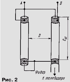
When connecting the antenna to the feeder using matching device "quarter-wave loop" as shown in Fig. 2, which is made of a short-circuited segment of the cable length lш equal to a quarter wavelength, which tuned antenna (taking into account the velocity factor). The distance D to range MV choose 50...80 and UHF range - 20...30 mm.
Another simple dish - the "half-wave vibrator Pistohlkors" [1, 2], presented on Fig. 3, has an input impedance at the resonant frequency 295 Ohm. As split vibrator, antenna made from tubes, rods or bands. The bending radius does not matter, the bends can be done at a right angle. The main advantage of the vibrator Pistohlkors before the split is that at the point of symmetry it has zero potential, and at this point it can be fastened to the mast without insulators. The vibrator is also placed horizontally in a plane perpendicular to the direction of reception.

The antenna has a wider bandwidth than split the vibrator, and different best noise immunity. Sizes l, L, d choose the same as for split vibrator. However, when calculating the velocity factor of the vibrator Pistohlkors instead of the diameter of the tubes take a value equal to twice the root square of the product of the tube diameter d on a size S in the vibrator. Last is $ 80...100 MV and 40...50 mm for UHF.
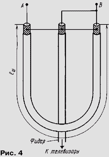
To connect the antenna to the feeder used is depicted in Fig. 4 matching the unit "U-knee", is made from a piece of coaxial cable with a characteristic 75 Ohm. Length lш equal to half the wavelength in which it operates the antenna divided by the velocity factor for polyethylene cable (1,52). The unit is connected to the vibrator at points A and B.
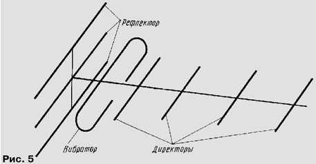
To reduce the influence of the reflected signal and slightly increase the gain of the the simplest of antennas, complicating them, for example, placing behind active vibrator (away from the telecentre) reflector, as shown in Fig. 5 for antennas "wave channel", which will be discussed below. The length of the elements reflector must be greater than the length of the vibrator l 5...15 %, and the distance from vibrator to reflector is chosen in the range 0.15...0.2 is the operating wavelength.
Loop antenna [1], is presented in Fig. 6 and 7, have a good parameters relative simplicity of the device. Their input impedance at the resonant frequency is 73 Ohms, the gain is 3.5 dB. Have them so same as the vibrator Pistohlkors, to obtain maximum signal level.
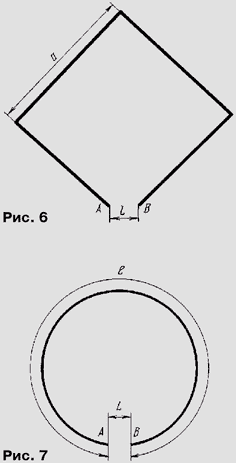
For incomplete zigzag antenna (Fig. 6) the distance and equal a quarter of the working wavelength. In the annular antenna (Fig. 7) circumference l equal to the wavelength at which it operates. For both antennas, the distance L is 10...for 15 MV and 7 mm for UHF.
Loop antenna connected to the feeder through a "quarter-wave short-circuited loop" (see Fig. 2). If on the side opposite to the direction of the telecentre, acceptance prevents a strong reflected signal, its impact can be significantly be reduced by placing the antenna behind the screen-reflector as shown in Fig. 8. This increases the antenna gain by about 3 dB.
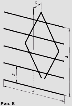
Structurally, the screen made of the same elements, and the very fabric of the antenna, but it is permissible to apply and more thin wires. Width a and height b of the screen on 5...10% more than the corresponding dimensions of the antenna. The distance D between screen elements is not more than 0.1 of the working wavelength, and between the leaf antenna and screen - 0,21 0,27...wavelength. The display elements are attached to the mast only center.
Full zigzag antenna depicted in Fig. 9, is also not difficult to manufacturing [1]. It is composed of two incomplete (see Fig. 6). Are tubes, rods, strips or two or three copper wires with a thickness of 2...3 mm, placing them in parallel at a distance of 5...10 for UHF and 20...50 mm for MV. The input impedance of the antenna at the resonant frequency is 73 Ohms. The coefficient gain - 6 dB.
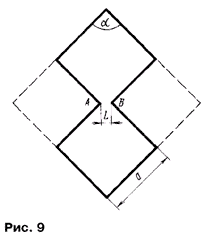
The antenna is connected to the lead-in cable without matching devices directly to the points A and B. the Feeder lay on one side of the antenna.
If you need to increase gain and reduce the influence of reflected signals set the screen-reflector the same way as for the loop antenna. Increasing the gain of zigzag antennas achieve using multiple systems, antennas with open extreme elements and with the angle a large 90° [3].
Antenna "triple square" [4] refers to the complicated designs and is a hybrid loop antenna and "the wave channel". It is shown in Fig. 10. Its input resistance is 70 Ohms, the gain is 8 dB. Antenna consists of three square elements: reflector (R), the active vibrator (In) and Director (D). Items made from rod, wire, tubes or bands cross-sectional dimension of at least 3 mm for UHF and 10 mm for MV. The sides of the squares R, and D is equal to 0.32, 0.25, and 0,22 working wavelength, respectively. The distance and between the reflector and the vibrator is equal to 0.16, and between the vibrator and the Director of b - 0,11 working wavelength.
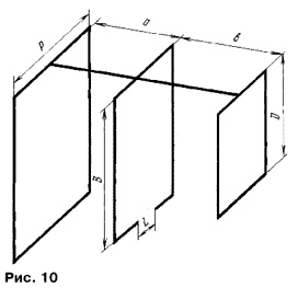
In the manufacture of the antenna plane of the squares should be parallel, and their centers on the same axis. To enhance the rigidity of the antenna by setting except for the top metal rungs, dielectric spacers between the squares. The distance L to MV is equal to 40, and for UHF of 15 mm. the Antenna connected to the feeder via matching device "quarter-wave short-circuited loop" (see Fig. 2).
The worst results in the simplification of the antenna can be obtained, refusing Director (antenna "double square"), but changing the direction of the reflector R and the distance and to 0.31 and 0.18 wavelength, respectively. Input impedance this antenna is about 100 Ohms, and the gain 3...4 dB worse than the "triple square".
For the more challenging narrowband structures include antenna "wave channel Spindler" [5], depicted in Fig. 5. Its input impedance at resonance the frequency is equal to 280 Ohms. The gain depends on the number of elements (see table).
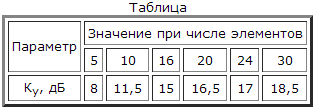
Such multiple-element antenna, in addition to the active vibrator, which is usually operate as a vibrator Pistohlkors, consists of several passive vibrators-Directors, with decreasing length of disposable active before the vibrator (in the direction of the telecentre), and screen-reflector affixed to the rear, in the direction opposite from the telecentre. It works on the principle of "running wave" and is considered the most effective narrow-band antenna. However, it is difficult in the calculations, and requires precision in manufacturing. Appointment of Directors - amplification coming from the main direction of the desired signal, and the reflector is weakening the reflected and other interfering signals.
Structurally, the antenna elements are fixed on a metallic or dielectric the traverse, which has the necessary mechanical strength. When applying metal traverses the length of the elements is increased by half of the transverse the size of the beam. To calculate the dimensions of the antenna using a complex formula or prepared computer program. One such program developed by the author and located on the site of the magazine "Radio".
In the manufacture of antennas, special attention should be paid to compliance with the exact the size of elements, spacing and symmetry of the antenna. Cable connected through a matching unit U-knee" (see Fig. 4) to points A and b vibrator Pistohlkors.
Broadband antenna designed to receive television signals significantly different frequency. They work well without rebuilding, sometimes completely overlapping ranges MV or UHF and even all TV channels VHF and UHF. The simplest of these broadband antennas are antennas types of climbing frame and zigzag.
The antenna design climbing frame shown in Fig. 11. Similar to the antenna described in [2]. Its gain is 1.5 dB, the input impedance is 73 Ohms. This antenna has a wide operating frequency range. However, due to low gain its use is limited to the range of MV. Orient the antenna the same way as any simple antenna.
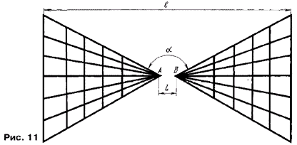
The antenna elements are made from copper wire or brass rod thickness less than 3 mm. At the connection of the wires provide a reliable electrical contact. The size of the antenna is chosen for the lowest frequency range, as for half-wave slotted vibrator. The corner solution a choose from 90 to 120°.
The antenna does not require a matching device - connect feeder directly to points A and B.
Zigzag antenna turns out small, if you use it for UHF. However, as shown by the studies described in [6], and extend its working bandwidth in a low frequency region, when used in construction additional elements depicted in Fig. 9 by the dashed line. In this case broadband zigzag antenna is calculated at the highest frequency of the received signal.
Very often (especially in remote transmitting stations areas) strengthening one antenna is not sufficient for reliable reception. In this case apply or antenna amplifier or antenna arrays [4]. Moreover, the use of the latter is more preferable, since any amplifier brings in useful signal additionally own noise and distortion, requires careful tuning with a fairly sophisticated measuring equipment.
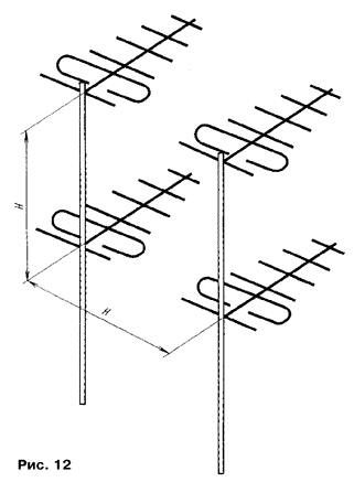
The simplest two-story lattice consists of two similar antenna, active elements which are located in the same vertical plane. The antenna should be spaced from one another (usually vertically) at a distance H equal to the working wavelength. The gain of this lattice by about 3 dB higher than the gain single antenna.
The best results can be obtained by using antenna array of four antennas, called two-storey double row, as shown in Fig. 12. In this case the gain increases up to 6 dB compared to a single antenna. The distance H is also chosen equal to the operating wavelength. Often the bars are from antennas "wave channel", rarely used loop antenna.
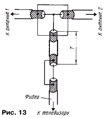
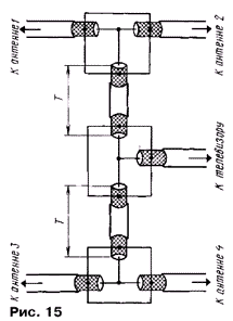
To sum the signals of the individual antennas of the lattice cables connect them through matching system, consisting of segments of coaxial cable with different characteristic impedance of a length T equal to half the operating wavelength (taking into account the velocity factor). The array consisted of two antennas connected to the lead-in cable through a section of cable with a characteristic impedance of 50 Ω as shown in Fig. 13.
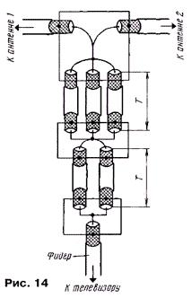
If you use a cable with a characteristic impedance of 75 Ohms, then connect the two antennas should be according to Fig. 14.
In the case of the lattice of the four antennas connection perform cable RK-75 in accordance with Fig. 15.
Literature
Author: V. Portnov, Bryansk


