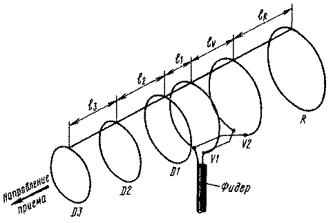
Antenna, schematic depiction of which is shown in the figure, represents "the wave channel" of the annular members for receiving signals in the UHF range. It consists of three Directors D1, D2, D3, reflector R and dual active vibrator V1-V2.

This antenna has good suppression of posterior lobe (up to 30 dB), the relative bandwidth of about 10 % and more gain than a conventional "wave channel" of the same length.
When you connect the cable from the bottom, as shown in the figure, the antenna receives signals with horizontal polarization. The length of the circumference of the antenna elements is determined from the relationship: R=1,08 l; V2=1,02 l; V1=0,98 l; D1=0,95 l; D2=0,94 l; D3=0,93 l, and the distance between them is given by:lR=0.2 l; lV=0,125 l; l1=0,06 l; l2=0,12 l; l3=0,23 l, where l is the average wavelength of the received frame (or channel) in the UHF range (it varies from 633 mm for the 21st TV channel to 382 mm for the 60-th channel).
Carrying a horizontal rod antenna with a length of about 0.75 l made of insulating material. For the manufacture of annular elements used is copper or aluminum wire with a diameter of 3...4 mm. Passive elements (Directors and reflector) can be made from strips of width 8... 10 mm. Distance between centers of conductors connecting line of vibrators is equal to two diameters of the wire. The antenna adjust the position of Director D1. Connection cable for the purpose of balancing it put a ferrite ring with a relative magnetic permeability of 400...600.
Ring sizes are not critical. It is fixed with insulating tape.
Author: N. Turkin, St. Petersburg; Publication: N. Bolshakov, rf.atnn.ru


