Described below is an experimental antenna (EA) has exacerbated another problem of electromagnetic compatibility of means of communication - the problem of sideband suppression of radio receiving devices. In the experiments with EA and the transmitter with a power output of 2 watts in the city have any complaints from the professional-commercial organization to interference from the radiation of spurious frequencies.
Follow-up audit of a scanning receiver in a specified frequency band (145 MHz) near the transmitter has not produced results. Previous work for two years at the same place and with the same equipment raises no objections, but the difference was only one or the other antenna: before the incident - "double square", then the described EA. The radiated energy dvuhletnego transmitter was so concentrated in the direction of the main lobe of the antenna, which equaled the level of the signal is mainly (not mirrored) channel commercial receiver, where the reception signal of the two-meter transmitter range is made possible precisely as if the transfer was conducted at a frequency of at 2Fпч above.
Asking radio Amateurs to pay serious attention to this problem: although it is, indeed, and "not yours", to fix it you have. as merchants (and their ilk) to do with this: they "paid money" and to fork over an additional high-pass filter or bandpass filter you can get.
After some measurements, the author (away from sin) decided to postpone the experiments with EA in field conditions - to the country. Since the antenna has a small size and very easily rolls up and deployed, transportation problem does not occur. A few words about why the "square" is selected as a portable antenna. First, it is twice shorter, for example, dipole antennas (in terms of length elements). Secondly (and this is important), "square" can be operated at very low altitudes suspension and insensitive to the surrounding objects (the effect of the hand, brought to the antenna side, affects only a distance of less 150...200 mm). Thirdly, such antenna to suppress local noise and impulse noise. Fourthly (author's version) has a closed DC active element.
A base for the construction of EA was fed by 75 Ohm cable "double square" [ 1 ] with the distance between the vibrators of 0.2 (see Fig. 1) whose elements (1 - active vibrator, 3 - reflector) were just hanging on the window pane 2 in the room.
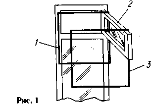
This "window"-the yoke can be fixed with hinges to the wall or corner of the balcony. The rotation of the antenna depending on the location of the reflector may be in the range of 120...150°. For mounting in a selected direction you can apply hooks and loops. This design, of course, taking into account specific local conditions, may be suitable for conferences, links, and reception of television.
How did EA described? In the room (the room on the second floor of a wooden house) was made to "stand" for experimental work with УSW antennas installed on the ceiling stretched two segments of thick fishing line at a distance of 250...300 mm from one another. To them using the rings from the same line or wires suspended from the elements (Fig. 2): first two, then three and so on up to 13 (so instead of bathroom). The length of the active elements of the vibrator (AV) and the reflector (R) were calculated by formulas from [ 1 ], and then tested with the help of the device measuring the frequency characteristics (ICH) XI -48. The Directors (D1-D11) is performed by reducing each subsequent (per side) 5 mm. the Material for the manufacture of elements - aluminum wire in PVC insulation from the three-phase cable APV (even better - a copper coated aluminum wire

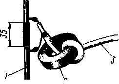
Fig. 3
in the same isolation that you can solder). The wire was not removed(elements with insulation white, black and red colours conveniently alternate - easier not to confuse them when tuning operations: using two elements, the difference in size becomes more noticeable). The lengths of the sides of the frames and the distance between them is shown in Fig. 2 (in brackets the values of their perimeters).
The input impedance of the antenna is about 45 Ohms. For power, the author developed a length of coaxial cable RK-50 with a diameter of 4 mm and a length of about 1 m (Fig. 3). In the connection of the vibrator 1 is mounted a ring 2 20 mm diameter ferrite VC, which made one coil a cable 3. You can apply and gamma-coordination (Fig. 4), which will align the antenna more accurately and to choose from, with both 50-and 75-Ohm cable. You can also for agreeing to move the first Director in relation to the active vibrator, and then pull up the rest of the Directors.
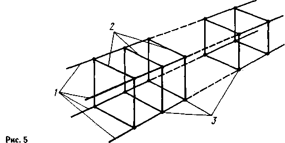
It should be noted that antennas with a large number of elements must be of rigid construction - the distance between elements in the process of operation should not be changed. As shown by experiments in the field, the two segments of line is not enough: the slightest breeze - and the antenna started to "play" elements swayed like underwear on the rope. The best option is a rigid cross member, but for field conditions is desirable, therefore, offer the design, schematically shown in Fig. 5: add two more cut 1 fishing line or string for tennis rackets, i.e. to increase this number to four. Stretches should stretch the corners inside the framework 2 and to fix the last (after final set-up), for example, using the same line (3), at the required distance from one another in accordance with Fig. 2. The length of line segments should be selected so that each end of the antenna was left on a 3...4 m to be attached to the supports, for example, to the trees.
To increase the reliability by the edges of the design to place the frame 2 (Fig. 6), made of wooden slats, attach them at the corners of the ends of the segments of line 5, and the frame to stretch the antenna using, for example, nylon twine 3 (here, 1 - bearing, 4 - element antenna). If one or both of the frames to make a gutter of wooden bars 4 (Fig. 7), the vibrators antenna 3 and stretch marks 2 can be put in them as in the case in the collapsed state and as such keep the antenna and transported to any distance. For mounting frame-cover 1 to the frame 4, you can use hooks or rings of electrical tape. The supply cable can be laid with the antenna around the perimeter of the framework or disabled (if releasable connector).
The antenna elements should be made of well-tweaked the wires. This is easily done by pulling, securing one of the ends in a Vice and holding the other in the pliers. Slicing of the workpiece, it is necessary to provide allowance for the connection (the twisting or welding) of the ends of the wire, for which they should be released from isolation. A small "tail" of twisted wires for the antenna to work is not affected, it is only important to observe the calculated perimeters of the frames. Places of connections of elements is better positioned with one side, e.g. bottom. In the plane of the framework should not be taught. Set them relative to one another should be strictly parallel, and "concentric" (when viewed from the side of the reflector).
To Orient the antenna for clarification on the Board on the correspondent can, as shown in Fig. 8, i.e., holding the wooden frame 5 (or a delay of 6) behind the reflector in this case the influence of the operator is minimal. Stretching 2 mounted on a wooden frame with 3 Directors 4 preferably bind to the supports 1. Finding the right direction to the correspondent, the frame is better to tie the corners of the antenna will be less spin in the wind. Experiment with EA (with vertical polarization) was conducted in the vicinity of the land, drained the swampy land in the valley. The upper part of the antenna elements is at the height of 1.8 m. EA has been stretched between the side of a barn and a small Board, dug into the ground as a support and reinforced by the antenna scarf. Distance to correspondents reached 22...24 km. In the "target" EA was the road, passing on the mound and sharing "target" in half, up the road about 200 m behind the forest 350...500 m (the situation is shown schematically in Fig. 9).
With careful manufacture and rigid structure of the EA is"spot", outlined the main lobe of (0.7) - 25...30°. In fuzzy setting items "spot" is blurred, and the gain drops. If it is not possible to ensure the mechanical stability of multi-element antenna (on four segments of line EA is quite hard) and sufficient accuracy of its manufacture, better to have four or five elements, and to manufacture them to take the wire of larger diameter. In this case, the antenna should be higher to avoid reflections from the ground near the antenna because of the expansion of the main lobe of the directivity diagram. However, to fasten elements still have quite tough.
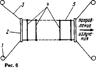
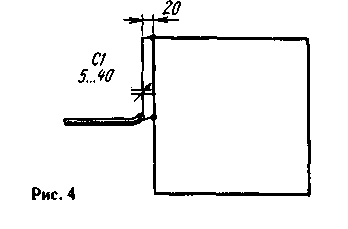
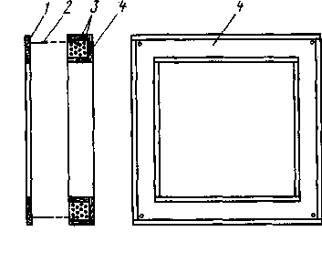
Fig.7
When working in the woods (especially in vertical polarization) should choose a sparse or open in the direction of the correspondent places (better yet - sublime), suspending the antenna between trees or pillars so as to avoid the presence of trees in the "target" of the antenna close to it. So, EA described may be folded and laid like a bellows harmonics. This is useful when you minimize, carry and quick to deploy, but is suitable only for relatively slow turning. However, if all be prepared in advance (hooks for attachment, for example), then the antenna can be rotated together for ten seconds, so you can use it in competitions "Field day" on the road. 13-element EA was calculated for operation at a frequency of at 145.5 MHz. With a little adjustment and even without it, the antenna can be used in all two-meter Amateur band. Strengthening EA - at least 15...16 dBd. The width of the main lobe of the directivity in the vertical and the horizontal plane is not more than 30° (0.7). The input resistance of about 45 Ohms, the SWR at the frequency at 145.5 MHz using coaxial cable RK-50 and matching device shown in Fig. 3, is 1.8.
Used methods of assessing the quality of the antenna - Amateur, approximate. In the experiments used foreign equipment: IC-706, FT-11, FT-270. At a distance of 24...25 km at low bridge EA and power 0.3 W correspondents gave the maximum score of 3-4 points on the scale of the existing S-meters. For comparison: in their instrument "opens" and "holds" the squelch and the intelligibility of the signal is 100 % when signal levels when the S-meter at all nothing shows. And you know, when hearing control 1 point reception is impossible, so that the signal level in the city was significant even at such low power. If you increase it to 4 watts maximum estimates were 59, 59+10 and even 59+20 dB! However, the latter "decibels" sometimes "was podmahivat". The experiment was conducted in the FM mode. For reception in the city was used for the vertical dipole, collinear antenna up and five vertical "wave channel" located on the roofs of houses, and in the far (from EA) end of town and the "wave channel" stood "a little sideways".
Noticed the influence of damp earth and vegetation propagation near the earth. Had to go to the rain and the sun peek out, as the strength of the signals dropped by 2 points. The estimated ratio of signal levels between the regular F-11 "rubber band" and EA: only "a change in the spectrum of noise is impossible to receive" - to 59 decibels, which clearly speaks in favor of EA.
Antenna "wave channel" on such a height would have been hopelessly upset. Large linear dimensions of the elements of such antennas require greater care in operation and greater height of the suspension, which is not always possible. Although when walking, probably to carry the"Yagi" in the collapsed state is more convenient, for example[2].
Experiment with УSW antennas, as mentioned above, it is possible to "stand" two stretched lengths of line. The elements di-dipole antennas, for example, just put the top and move relative to each other during adjustment. From a random offset they can fix any of the clips, for example, plastic linen clothespins with cuts. As a model you can use the signal "beacon" [W] specified in the "target" of the antenna in the center of the main lobe of at least 10 lengths of the beam (the distance from the reflector to last Director).

The cable from the active vibrator is connected to the input of the receiver, the settings are at the maximum of the signal "beacon". Similarly, you can "work out" directional antenna for receiving television signals for reception zone. The cable from the antenna in this case is connected to the TV, and are setting, achieving maximum contrast and minimum noise (moire) on the screen, and better controlling the AGC voltage. The sequence settings are. First pull of line-beam in the direction of the telecentre, suspend the active vibrator and connect it to the TV. Then behind the vibrator install the reflector and draw it traverses to obtain the maximum possible signal level (perhaps it will just increase the noise in the channel, sound). Securing the reflector in place, install the first Director and thus achieve a further increase in the signal, then the second etc. until the last Director.
Next, specify the direction of the telecentre, the rotating beam from the reflector, and then adjust the position of all the elements of the antenna for maximum received signal. In this way the author was executed ten elements antenna on the sixth television channel for reception of transmissions in the mountains of Karachay-Cherkessia (taken reflected from signal mountain). For lack of a suitable active material, the vibrator had to be cut from a sheet of duralumin (vibrator Pistohlkors).
A few words about the power cable is connected to the active vibrator. At the break in its middle set of the dielectric insert, which is fixed to a coaxial cable or coaxial socket plug connector. For rapid manufacturing of the antenna is possible, applied by the author: the active ends of the wires of the vibrator are bent at right angles, flattened for better fixation of the cable, and then impose one on another (insulation for insulation) and fasten the bandage of durable - nylon, Dacron or the usual "harsh", impregnated with bitumen - thread (wire is not recommended, as the bandage from her gives spurious re-sonance in the electromagnetic field of the antenna). Frame with slightly deformed, but it's not terrible, it is only important to the work perimeter of the vibrator was equal to the calculated one. To the ends of the vibrator supporter of single-conductor tinned wire is attached sheath and the Central conductor of the coaxial cable, previously passed through ferry Tomoe (WC) ring outside diameter 16...20 mm (Fig. 3). At the other end of the cable mounted plug coaxial connector for connection to the antenna Jack of the radio station.
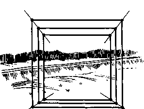
The polarization of the antenna can easily be changed by deploying 90°, only the active vibrator (the other elements do not need to touch). A disadvantage with this structure gives no compensation for the weight of the cable in vertical polarization. At small length is no problem - the operator holds the cable itself, at a large. the length has to maintain its additional fork stuck in the ground near the active vibrator. The cable is preferably positioned perpendicular to its side (for vertical polarization it must be placed strictly horizontally). The author hopes that the simplicity of design and manufacture are described EA encourage radio Amateurs on their own experiments with aerial equipment, it is known that the best RF amplifier is a good antenna. This antenna will allow you to feel much more confident in the campaign, in the country, in short, anywhere you need to provide reliable communications low power at large ("the standards" УSW and QRP) distances. Because low power - small size of the equipment and, most importantly, the sources of its power. Remember the results of the tests listed above: the only change in the spectrum of noise on regular radio antenna at an output power of 4 W and 3-4 points at "rough" S-meter at 0.3 watts - the difference is significant!
The antenna is called experimental - Amateur radio operator will decide how best to manufacture from available materials. In marching version (without wooden frame or box and cable) it weighs less than a kilogram, convenient to carry - with one hand and can be worn antenna and the bag (inside framework-vibrators), and the ends of the forest to traverse it is easy to gather in a bunch and temporarily secure rings PVC electrical tape or KLT. The antenna allows to be around her (on the side) at a distance of 150...200 mm, which, in turn, allows to use a short cable. Equally important is the fact that it is running fine at low altitudes suspension (although much height, if circumstances permit, does not hurt). In practice, the upper edge of vibrators shall be at a height of not less than 1 m (1.5 to 2m) from the ground. The distance between the vibrators selected based on their easy remembering that simplifies the manufacturing of the antenna as needed (impromptu), and if necessary adjusting the position of the vibrators in their accidental displacement.
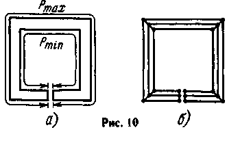
Note that when used for the manufacture of the uneven part (neutralising) wire the error, which is expressed in the elongation of the perimeter elements. The use of thicker wire increases its own capacity framework, which requires a corresponding reduction in their perimeter. Approximately the bandwidth of F (in megahertz), which increases with the diameter of the conductor frame (including in the form of a tape), can be calculated using the formula given in [1]. For example, for the active vibrator F - Rmah - Fmin - 304635/Pmin - 304635/Rmah, where Fmax and Fmin are the upper and lower frequency limit of the bandwidth, the minimum and maximum perimeters of the frame (Fig. 10).
Belt vibrator can be modeled from several wires, electrically connecting them with each other (Fig. 10, b) than for a long time and successfully used in the manufacture zigzag TV antennas. Sometimes, making the antenna according to the description, it is better to slightly increase the diameter of the wire elements, and, thus, the "remaining" bandwidth, somewhat lost in the antenna gain.
I take this opportunity to Express my gratitude to render the author (wittingly or unwittingly) help in the experiment: RA9LO, RA9LZ, RA9LE, UA9LFJ, RA9LT, UA9LAJ.UA9LP, UA9LDG, RA9LY. UA9LAC, UA9LR, RA9LAP, UA9LBG and hams Sverdlovsk region, setting a repeater (channel IARU R1 145025 kHz - TX/145625 kHz - RX) and prompted me to this venture. After long vigils during the experiments with EA I managed to find fuzzy signals S2 QSB repeater. But for the transfer, of course, two watts is not enough (300 km QRB) to open the repeater. I had to make a sound generator of sinusoidal oscillations at the Electromechanical filter AF frequency 1343 Hz and a bandwidth of 9 Hz (SI.067.064 on THE radio "Kama"), so that when "open" repeater Sverdlovsk stations over a voice could "climb" weak telegraphic signal.
But there it was. It takes time and a great passage that is "once a year", for example, in November 1996, when they worked FM directly and without repeaters. Meanwhile, applying FM telegraphy and clicking on the vocal cords, I could only shout to our "firms". They appreciated the quality of my EA and called a safety point of Gosvaiznadzor, since the level of my signal (in the direction of Ekaterinburg, and in the experiments - Yves other areas) were offset suppression frequency two-meter Amateur band input circuit of the receiver (image rejection). The experiment had to be stopped.
A few words about other experiments with the framework antennas. Tests of the two-part "double square" has shown that for communication inside the city it is perfect as a "non-directional" antenna with vertical polarization at the transmitter power 1...5 watts. When set higher above the roof, he "gets to the ground" in either direction when receiving and when transmitting (the experiments of the author with UA9LFJ). The acquisition of omnidirectional antenna properties due to pereizlucheniya, reflections, e.g. from buildings, wires, metal poles and other structures.
When using this antenna on the edge of town takes effect of its radiation pattern, having a fairly wide (about 60° to 0.7) of the main lobe and the gain about 8 dBd (when the location of the reflector at a distance of 0.2 from the vibrator and the input impedance 75 Ohms). Due to this turning the antenna is not necessary, enough to send her over the town.
When removing from the city the latter takes less and less angle on the horizon, and the level of the signal decreases proportionally to the square of the distance, which corresponds to a narrower main lobe of (higher gain) antenna with a high number of elements.
Tested and semielemental EA, located inside a wooden shed. The width of its main lobe is equal to about 40°, and the gain is about 12 dBd.
As it turned out, the impact on the setting of the active element (in terms of resonant frequency and input resistance) of the fourth and subsequent Directors can be ignored and the number of them to choose according to needs. In addition, you should remember that if the number of Directors although you can focus the energy to a small "spot", but not for long and "fluff" in the direction of the correspondent both in azimuth and in elevation. At the same time, multi-element antenna capable of operating at a lower altitude. Marked increase of the signal at one point when lifting from EA original height of only 300 mm. When changing the polarization on the horizontal (from the correspondent vertical) signal strength drops to four points. More precise matching of the antenna feeder can be achieved by moving a ferrite ring on the cable.
Some lower secondary elements EA and the rise of the last Directors (due to sagging traverse out of line), and the suspension upper sides of the elements at the same level (concentrace) creates additional conditions to a small elevation of the main lobe of the directivity diagram. It also promotes the possibility of low suspension above the earth's surface without the risk of reflection and scattering of concentrated RF energy near the antenna. However, the terms of the distribution of this energy over the surface of the earth remain within the aperture of the main lobe,
Literature
- Rothammel To, The Antenna. Moscow: Energiya, 1979. P. 267, 268.
- Rothammel K. Antenna. Moscow: Energiya, 1979. P. 232,233.
- Besedin V. УSW Beacon. - LW journal, 1998,No. 2,pp. 46,47.
- Besedin V. Adaptation of radio stations industrial applications for Amateur conditions. - Ham. LW and УSW., 1996, N 6, p. 26.
Author: Victor Besedin (UA9LAQ), Tyumen; Publication: www.cxem.net


