Currently ham radio operators are increasingly embracing УSW ranges and 1296 2400 MHz. The latter, for example, is used to receive signals from the repeater Amateur radio satellite AO - 40. The setting of the equipment and antennas high frequency УSW ranges greatly facilitate low-power transmitters - beacons.
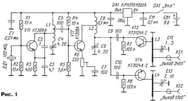
The circuit of the radio transmitter shown in Fig. 1. It consists of a master oscillator with quartz frequency stabilization, assembled on the transistor VT1, buffer the amplifier transistor VT2 and two varactor frequency multiplier using capacitance collector transitions of transistors VT3 and VT4. The required harmonic components are allocated resonant circuits L3C12 (2400 MHz) and L4C13 (1300 MHz). The antenna connects to a coaxial socket connectors XS1, XS2. Generator and amplifier are powered from the battery GB1 integral voltage regulator, assembled on a chip of DA1.

Device works well. The master oscillator is oscillating at a frequency of quartz resonator, in this case 100 MHz in the circuit of the base of the transistor VT1. In the collector circuit of the transistor is set contour L1С4, and the positive signal fed back to the emitter circuit through the capacitive divider SS.
The signal from the parts of the turns of the coil L1 is supplied to the resonance amplifier, made on the VT2 transistor. His gain is infinitely adjustable resistor R6. The amplified signal from the circuit L2C6 comes to Barak-vector multipliers frequency. The 24th harmonic of the signal (2400 MHz) is generated at the nonlinear capacitance the collector junction of the transistor VT3, is extracted by the contour L3C12 and arrives at output connector XS1. Quite similarly to the 13th harmonic (1300 MHz) have a chain of nonlinear capacitance of the collector junction of the transistor VT4 and allocated circuit L4C13. In these resonant circuits half-wave applied the resonators.
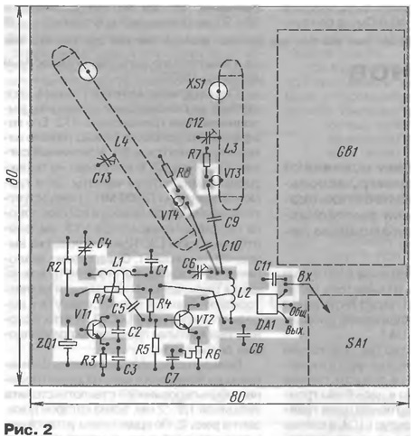
Most of the details of the beacon placed on the circuit Board from double-sided foil fiberglass with a thickness of 1.5...2 mm, a sketch of which is shown in Fig. 2. On the edge of the PCB is a metal screen with a minimum height of 20 mm, which is closed by a metal lid. The switch is set on the screen, and output connectors directly on the Board.

In the device, except as indicated in the diagram, it is permissible to apply the following details: chip voltage regulator - 78L05, transistors VT1 and VT2 - CTB, and VTЗ VT4 - CTA. Trimmer capacitors C4 and C6 used type CT - 25, C12 and C13 - CT - 27 (without pins), fixed capacitors - K10 - 17B (without pins) or K10 - 17A with the conclusions of minimal length. The trimmer - type SPZ - 19, fixed resistors - MLT, P1 - 4, P1 - 12. Coils L1 and L2 frameless, they wound wire sew - 2 0,6 mandrel with a diameter of 5 mm and contain 6 turns with taps between 1 and 2.5 turns and 2.5 turns, respectively, measured from o, connected to the power wire.
Half-wave resonators L3 and L4 are made of copper strips (preferably silver plated) foil with a thickness of 0.5 mm and a width of 6 mm in the form of the letter "P". Top part has a length of 25 mm (L3) and 45 mm (L4), lateral parts - Connectors 5 mm. connected to the upper part at a distance of 3 mm from the lateral parts, and the transistors VT3 and VT4 - 5 mm, as shown in Fig. 2. Trimmer the capacitors are soldered vertically in the middle of the top.
Output connectors applied type SMA or similar, definitely high-frequency, coaxial. The switch SA1 can be any small. The device is powered by battery with a 9 V type "Krona", "Emery", "nick" or similar, supply current is 10...12 mA.
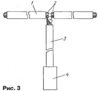
As an antenna you can use a quarter-wave segments of a hard wire or half-wave vibrators, the design of which is shown in Fig. 3. They made the segments of the cable RK50-2-22 or similar. The vibrator 1 is made of cut a length of 55 (2400 MHz) or 105 mm (1300 MHz). At the ends of the cable segments trimmed by 1.5...2 mm, braid and center conductor interconnect by soldering.

In the middle of the vibrator on the length of 4...5 mm remove the outer insulation and accurately cut the braid 2 to form a gap between its parts about 2 mm. Then braid the incision tin and soldered to the second feeder cut the cable 3 to the connector 4 on the end to one side of the vibrator braid, and the other center conductor. Recommended length (with connector) feeder segments 90 (2400 MHz) and 165 mm (1300 MHz).
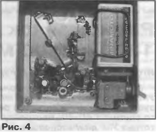
Photograph of mounted radio transmitter (with removed top cover) is shown in Fig. 4.

The establishment of the beacon start with tuning the master oscillator and buffer amp. Construction of the resistor R6 is set to the middle position, trimmer capacitor C4 to achieve sustainable energy generation, and with the help of trimmer capacitor C6 is the maximum of the signal at the output of the amplifier. Then customized for the capacitors C12 and C13 set up a half-wave resonators on the appropriate frequency to the maximum output signal at the desired frequency the harmonics.
In conclusion, the resistor R6 sets the maximum level of harmonics on the outputs, thus spend additional tuning circuits using rigged capacitors C4 and C6. If the amplifier will be unstable between the collector of transistor VT2 and outlet of the coil L2 must be installed resistor 50...100 Ohms.
The output level of the configured beacon on 50 Ohm load was 50...70 mV (1300 MHz) and 5...10 mV (2400 MHz). In most cases, such a signal enough, because of the high frequencies (and therefore small wavelength) remove beacon at a distance from customizable equipment is not make much sense.
Author: I. Nechaev (UA3WIA), Kursk


