


")

The design is simple and effective in the work of the CBS antenna is shown in Fig. 13. Here: 1-carrier antenna - sliding telescopic fiberglass rod length of 6…8 m; 2 - thrust bearing; 3 - backstay (hard) that secure the antenna in position; 4 - vibrator antenna - wire MAR or mgshv section 0,5…1,5 mm2 and a length of ~levels lower than the 5.37 m attached by a tape to the end of each segment of the rod 1; 5 - matching device in the waterproof cover; 6 - feeder - 50 Ohm coaxial cable; 7 - 5…10 ferrite rings (m=50…2000), pulled over coaxial cable.
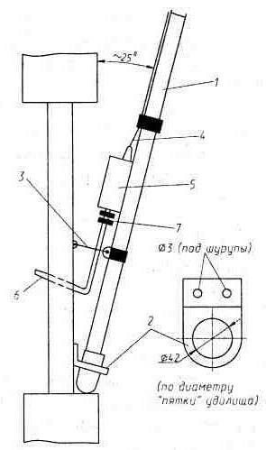
Fig.13. "Window" CB antenna
A schematic diagram of a P-loop, matching the high input impedance of the antenna (it is oscillating in antinodes of voltage) with a 50-Ohm feeder, shown in Fig. 14. Coil L1 - frameless. Its 9 turns wound wire sew-2 1,6 on disc diameter 8 mm and stretched to 19 mm Capacitors P-outline - any high-frequency (with low losses at frequencies CB) having a sufficiently high operating voltage. The latter refers primarily to the capacitor C1*. Its working voltage Uс1і12(C2/C1)Cruich where pout is the transmit power in watts, and Uс1 - volts. So, when pout= 4 W Uс1і100В, pout= 10 W - Uс1і160B, and when pout=100W - Uс1і500 V. And if 4…10-watt transmitter as C1 in the P-loop would do, for example, capacitor type KCO-1 (250 V), 100 watt - CSR-2 (500) or more high voltage.
Coil and capacitors P-outline raspalaut on single-sided PCB, made of foil fiberglass thickness of 2 mm (Fig. 14, b). Assembled Board with soldered to her end of the vibrator is introduced into fused from high impact polystyrene box case without the "bottom" (Fig. 14,) that protects it from rain and snow.
The feeder of the antenna is 50 Ohm coaxial cable. At a length of 10…15 meters, he can be quite thin. So, in the cable RK50-2-16 (outer diameter 3.5 mm) loss at frequencies CBS will not be negligibly small 1…1.5 dB. Savings in weight of the antenna-feeder the system can be important, for example, in Hiking expeditions.
Cable length recommended take a multiple of l/a where l is the wavelength, corresponding to the middle of the range operating frequency, and e is the dielectric constant dielectric coaxial cable (for polyethylene TSE=1,52). That is, its length may be equal to: 3.6; 7,2; 10,8 meters etc. Under such the lengths of the cable may have even more characteristic impedance.
The antenna set up regular way. Inserting a SWR meter between the feeder and the radio station, working on the transmission in the middle of the range of operating frequencies, and shifting is pushing the coils in coil P-outline (Boxing-case is shifted by a vibrator), try to obtain an SWR of 1. If you do this fails, looking for the frequency (you need to have a multigrid station), which this turns out. If the frequency corresponding to VSWR=1, was lower than the mid-range frequency vibrator pruned, if the above - lengthen. The magnitude of the lengthening-shortening M is calculated by the detuning of the antenna: the detuning Df =100 kHz corresponds to Dl=2,5 see
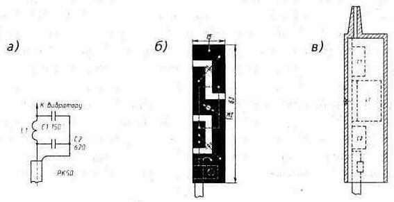
Fig. 14. Matching P-loop: a - scheme of a P-loop; b - circuit Board; - box-cover
As experience has shown, stripe operating frequency of the antenna 300…400 kHz (VSWR <1,5).
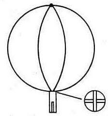
Fig. 15. "Globe", expanding the bandwidth of the antenna
The antenna can be supplemented wire the "globe" (Fig. 15), made of two 43-inch lengths steel cord** cross-section of 0.8 mm2. They are pre-tinned with good flux the ends raspalaut in a cross sectional view connector socket connector type SR. On the other hand in the socket solder the end of the vibrator shortened 5…10 cm (need shortening specify when setting up the antenna).
Soldered to the vibrator the globe is attached to the tip of the rod with electrical tape. Lightness and small windage make this mount is sufficient.
Antenna wire "the globe" at the end of the vibrator has significantly more bandwidth and less addictive The CWS of the operating frequency.
In urban environments the antenna can be installed directly outside the window of his apartment as shown on Fig. 16 (antenna derived from the field of view of the upstairs Windows). The angle between the wall and rod should be in the range of 20…30°. The antenna is better to put on the window, facing the most interesting correspondents.
Of course, the radiation pattern thus the installed antenna will affect metal wall fittings, shielding and absorbing the impact of the whole building. But, as experience shows, its difference from the circular largely offset the same city terms - multipath signals of the neighboring buildings. Although in itself asymmetrical directivity the disadvantage of the antenna, of course, is not.
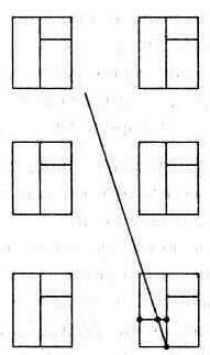
Fig. 16. Mounting the antenna on the window
On a country house or at the cottage the antenna can be put vertically. Inserting, for example, the handle of the rod into the slot in the attic window. The fishing rod with a pre-fixed his sections of the dipole antenna and box pushing in the installation process.
Can you recommend another method. The handle is fully deployed, the rod antenna is secured with two hose clamps on thin end 5…6-meter pole. Close to home in the land of make cylindrical, the diameter of the thick part of the pole, the notch depth of 10…15 cm and by inserting in it the pole, raise the entire structure (it weighs 5…6 kg) in a vertical position. In the upper part of the pole is attached to a protruding part of the house: tie to the eaves of the roof to the rafters, etc. In this variant, the antenna can be installed outside of any buildings, only need another reinforcement of its pole-masts.
The antenna is not required to lift, if it is mounted on a sliding fiberglass rod length 11…12 m. To lock the antenna in a vertical position rather attach it to the rack expedition tents or to hammered into the ground dural corner.
If the antenna deploys on the edge of the forest, here, as a rule, it is possible to use a suitable tree. Through its branch situated at a height of 11…12 m, throw*** nylon the line, which troubles him the whole antenna system - a vibrator with hanging it Boxing of the P-loop and part of the feeder. Just need to leave between the tree and the top of the vibrator (having at this point is the antinode of the voltage) 10…15 cm cut the fishing line as a high frequency insulator.
Height 11…12 m (~l), which was recommended for this dish in all its varieties, is not accidental. At this height suspension vertical half-wave vibrator over a conducting surface, its radiation at small angles to the horizon, need for communication with the correspondent of "earthly" wave reaches its maximum (minimum become radiation loss for the other angles). But this is only true for distances between correspondents r, not exceeding rmax@ 4(T+C), where rmax is the maximum distance "range" - in km and h1, and h2 is the height of antennas correspondents in m. If r I< rmax, then the antenna set at rmax, as the suspension height of the antenna will play a big role here than the best "adherence" lobe of its radiation to the horizon.
If the conditions no need to keep the antenna on the street constantly attracting unwanted, perhaps, among full-described antenna has not, perhaps, equal: the Assembly and disassembly takes less than a minute.
As shown by long testing (radio Yosan-2204, Dragoit SY-101, etc. without any amplifiers), antenna, both in urban and rural variants allowed keep confident connection worldly wave at distances up to 30…40 km or more. And the "aisle" - with all the regions of the European part of Russia, Ukraine and Belarus.
*) For higher frequencies criterion in the selection of capacitors for antenna circuit becomes reactive power and dissipation factor.
**) This cable is used for decorative upholstery soft doors.
***) For example, using slingshot; the projectile may be 20 to 30 gram fishing sinkers attached by the end of the line.
Publication: www.cxem.net