


")

Almost any owner of a CB radio comes with time necessary to install a good stationary antenna. However, in urban environments it is not always easy, since it is necessary to solve at least three problems : the legal ( in terms of authorization and access to the roof ), mechanical ( providing the necessary wind resistance) and vandal ( fight for the safety and serviceability of the antenna and cable ).
Obviously, in some cases, these difficulties can be avoided if to refuse from the antenna on the roof and to use variations of a balcony or even podokonnikova antennas. Of course, their effectiveness largely depends on the height of the suspension above ground level , but with the right build you can achieve good results and receive antenna with very good parameters, able to work well even at the level of the second floor.
It should be noted that in this case it is not about the balcony aerials class "BOOMERANG", which is not widely used because of its low settings ( band level VSWR =2.0 not more than 30 … 35 channels, the minimum SWR is very difficult to drop below 1.3 ), as well as some design flaws - weak attachment point and the relatively large length of the pin (the upper part almost looks in the window of the upstairs neighbor). Readers are provided with the description of the simple antenna that is easily mounted on podkonice, the balcony, etc. and has a relatively good parameters. This table is based on the idea of an ordinary car antennas - short pin with a lengthening autotransformer coil and a matching unit.
There is a widespread belief that the car antenna with magnetic mount cannot be adjusted without a substantial counterweight, which is the body of the car. Actually it is not. The difficulties usually associated with the fact that the resonant frequency of the antenna while reducing the counterweight moves upwards and beyond the ST range. In this case due to the large mismatch begins to radiate and the antenna cable, which complicates the measurement and leads to conflicting results when trying to configure the entire system. Not difficult to see that by placing the antenna on the window sill and extending it in any way at 25-30 cm, you can seek the dismissal of resonance back, however, the minimum SWR is thus likely to be unpleasantly high. Indeed, a longer antenna has a higher input impedance and requires additional coordination with lead cable.
Thus, there is the possibility of using a standard automotive antenna as stationary. Necessary modifications in this case are reduced to the prolongation of the pin ( in the simplest case, using a conventional "crocodile" and a piece of elastic wire ) and increase of 0.5 … 1.5 round bottom matching autotransformer. To fine tune the antenna you can use the technique below.
At the same time, a similar path is unlikely to be warranted. First, it is a pity to spoil a good thing and, secondly, not all antennas can safely be disassembled to gain access to the matching device. Therefore, the following describes the design simple homemade antennas that does not contain any expensive units and allowing for the known variation in size of non-essential details.
The antenna design with indication of the main dimensions shown in figures 1 and 2. As can be seen from the drawings, the antenna consists of the following blocks: composite pin ( 1,2 ), block balances ( 3,4 ) , a matching device ( 9 ) and rod fixation elements ( 5,6,7,8 ,10).
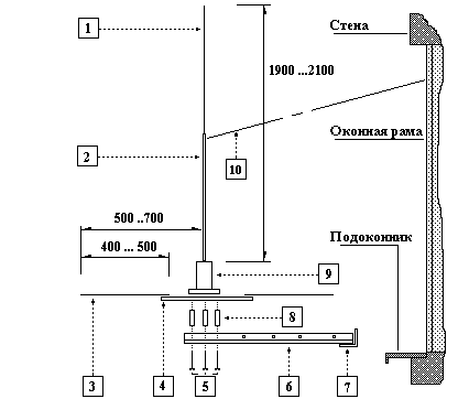
Fig. 1. Antenna design - side view
Composite pin is a metal tube 2 diameter 7 … 9 mm ( preferably of copper or duralumin ), in which is inserted a steel wire with a diameter of 2.5…4 mm. This design allows to obtain high mechanical strength and easily change the length of the antenna.
Block counterweights made of foil-coated fiberglass ( thickness 3 .. 4 mm ) in the form of a circle 4 to which is soldered a wire beams 3. For their manufacture may be used copper wire with a diameter of 2 .. 3 mm.
For mounting the antenna used T-shaped rod (6,7), is made of three metal corners, bolted screws. Area 7 is used to fasten the rod to the bottom Board of the window frame. The unit balances is screwed to the rod through the bushing 8 long screws or bolts 5. To give greater rigidity to the entire structure, it is desirable to rastrapati antenna pin wooden slats 10, as shown in Fig . 1.
More detail should dwell on design matching device, which is shown in figure 3. The Central insulator ( phenolic resin, ebonite, etc.) with a diameter 18-22 mm wound coil of the autotransformer . On its shaft inserted two threaded studs fixed with brass screws that serve both sites for what you have! wires and antenna cable. On top of the pin, either directly or through the threaded sleeve is screwed a pin of the antenna, and through the lower studs matching device is screwed to the unit balances. Preferably close to matching device above any non-conductive casing - for example, a plastic beaker of suitable size.
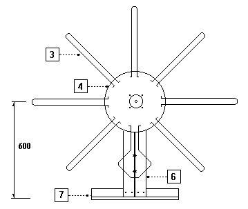
Fig. 2. Antenna design - top view
For the coils of the autotransformer should be used a copper wire of diameter d is not less than 1.5 mm Place of what you have! Central core of the cable may vary for each particular antenna, so you must strip the insulation at several points. When assembling the antenna should pay special attention to the reliability of all electrical contacts and resistance.
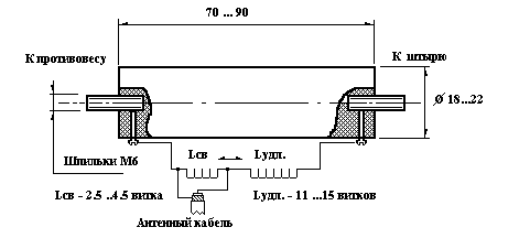
Fig. 3. Matching device.
The following table lists the design parameters of the matching device, providing a fine-tuning of the described antenna:
D D Nсв of Nудл 19 1.8 3.5 8.5The antenna tuning is performed in two stages. The first of these is training and can occur directly in the room. In homes with reinforced concrete slabs antenna should be raised above the floor to a height of 30 … 40 cm To reduce the influence of reinforcement on the properties of the counterweight. It is desirable that the upper end of the pin was located as far as possible from the network of wires and the walls of the room. The actual setting of the antenna is to change the length of the pin and measuring its VSWR over the widest possible bandwidth. You should not be lazy and be limited to two to three dimensions, because at this stage it is important not the absolute value of the CWS, and the elucidation of trends in the frequency band. It is desirable to record the data, because the difference in values can be very small. The purpose of these measurements is to find resonance and shift it in the middle of the desired grid frequency by changing the length of the pin. It should be remembered that the decrease in the value of VSWR with frequency (in the direction of the grid (F) requires lengthening of the pin, and Vice versa. When the successful outcome of this operation have the selection of the connection point of the antenna cable to the autotransformer matching device to achieve a minimum SWR at resonance. Additional sign of a successful tuning stability is the VSWR at various positions of the cable and touch the hands of the housings of the radio and SWR meter.
Note that when installing the antenna outside the window, its settings will change. Therefore, at the first stage it is desirable to provide the possibility of tuning of the matching device. For this purpose it is possible to recommend a method of tuning using closed-loop, as is done , for example, in some stationary antennas. This should really not fear that the efficiency of the antenna from this, allegedly, is sharply reduced. Well made closed loop - strips of thick copper foil with a width of 15 … 30 mm, carefully soldered in place of the joint, has a very small resistance and slightly reduces the quality factor of the system. In practical terms, you need to ensure that this ring is as close as possible to the coils of the coil, was well insulated from it and was able with little effort to move along its axis. Below we will illustrate the process of configuring the antenna in this way.
After fixing the antenna outside the house need to repeat the configuration procedures. In the case of particularly incorrect settings inside the building may be required as the change in the length of the pin and the soldering point of the drain matching device, but it should not cause difficulties with the lessons learned in the first phase of the experience.. it is Recommended to adjust the antenna to resonance in the grid and using a closed loop shift it up in frequency to the desired channel. After completing the setup process, you need to close matching device casing and make sure the mechanical fortress and suspension struts.
Frequency response describes the antenna shown in figure 4. The measurements were carried out in the following conditions: the power level is 10 watts ( p/St. Dragon SY101 + PANDA 10ST) and SWR meter SWR-430.
In the same figure shows the characteristic of the antenna "BOOMERANG-SYRIO -27A"( type - GP, the total length of 3.2 m). The comparison proves the certain benefits of homemade antennas. In practical tests, this antenna being installed on the twentieth floor level, provided an increase for reception of distant ( 55 ..65 km) correspondents to 2 points in comparison with an antenna similar to the antenna "BOOMERANG-SYRIO".
And, lastly, again on configuring the antenna short turns. Figure 5 shows the corresponding change of the frequency characteristic of the described antenna at a fixed length of the pin. The figure shows that when the sliding loop on matching device resonance is shifted in the right direction and working multiple band antenna extends.
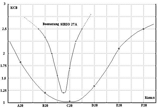
Figure 4. Comparative characteristics of antennas
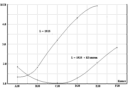
Fig. 5. Antenna configuration using the fault-loop
Publication: krasnodar.online.ru/hamradio, www.cxem.net