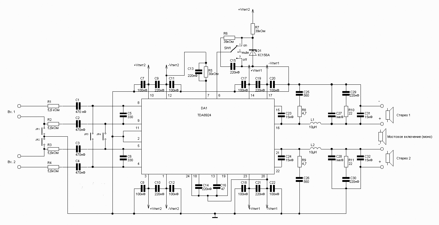
Main features are as follows: The voltage, V +/-12 to+/-30
Supply current (no signal), 100 mA
Output power(max) W:in stereo 120
in mono mode 240
Efficiency, % 90
The chip also has short circuit protection, output, thermal protection and protection of acoustics from "boom-boom" when turning on and off. In General, to burn her pretty hard. Well, of course, comrade manufacturer thoroughly disingenuous, when exhibiting such values of output power. The fact that they are given harmonic distortion of 10%, which is a complete mess. But, nevertheless, the amp worth getting looked at him closer, even soldered. But actual power values will be discussed shortly, after a look at the diagram.

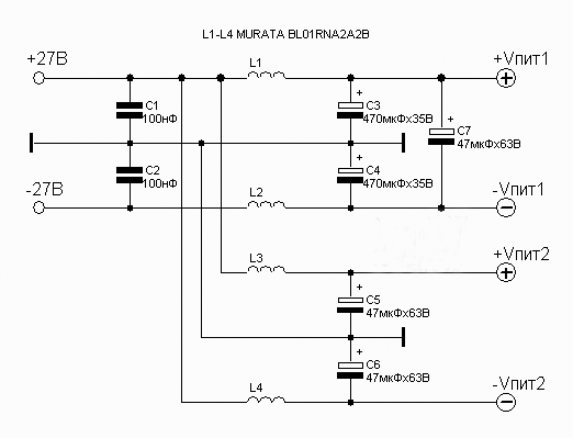
The scheme provides for two options for turning the amplifier - both stereo and mono, pomostowe scheme. Particularly useful, in my opinion, to use this amplifier for Subwoofer - Douri he is very good. Speaking of dope. Agree, 10% is a bit much. However, with reduction of the harmonics falls and the power output, but luckily for us not catastrophically. Under reasonable 0.5%, the amplifier gives to the load 4 ohms 70 watts in stereo mode and 200 watts in mono mode. By the way, in stereo mode, you can connect it to a 2 Ohm load, then he will give 95 watts for the same 0.5% distortion. The transition from stereo mode to mono is as follows: reconnect acoustics, closable jumpers JP3 and JP4 and remove the components R3, R4,C3, C4 and C6. Power to the amplifier is connected according to the following scheme:

All this can be mounted on the same Board, size is not relatively small, especially as the heat sink for the chip need purely symbolic. About one kilogram of aluminum hanging on the flange of the chip, as is the case with conventional amplifiers can be forgotten. All the inductors, which are used in this scheme you can buy ready-made. L1-L4 is the chokes with a current capacity of 4-5 A. L1 and L2 of the amplifier - inductance of 10 µh, with a current capacity of 6-7 A.
Now the list of features is quite extensive, but the same type:
The symbol in the diagram is the Value
C1, C2, C3, C4 - nF
C5, C6 - 330
C7, C11, C17, C20, C8, C12, C18, C22 - 100
C23, C24, C32, C31 - p
C25, C26 - 560
C28, S - 1uf
C30, s, C9, C19, C15, C13, C10, C21, C14 - nF
C16 - 47
D1 - XA
L1, L2 - 10 µh
R1, R2, R3, R4, 5,6 kOhm
R9, R8 - 4,7
R10, R11 - 22
R6, R7 - am
R5 - 30kom
DA1 - TDA8924
Power source
C1, C2 - nF
C3, C4 - mV
C7, C5, C6 - Thu
L1, L2, L3, L4 - MURATA BL01RN1A2A2B


