Case without rear wall
The main resonance frequency of such a case

where I is the depth of the drawer, m; S - area of the hole, m2. The increase in acoustic power at the fundamental frequency of resonance of 3-6 dB at a relatively flat and 6-10 dB at deep-sided case attaches studied sound unnatural timbre. If Fi = fГ , the increase in acoustic power at low frequencies most significantly. It is advisable to use a speaker with a frequency below the resonance frequency of the resonance box; most common ratio fГ / Fi = 0.5 to 0.7.
Case without rear cover as acoustic design in high-quality playback systems not currently in use. If there is no alternative, the case should be flat as possible. Case without rear cover with loudspeaker should be placed no closer than 20 cm from the wall, which is recommended to shadenfreude heavy carpet. If the loudspeaker should be placed along one wall, preferably along a short, closer to the middle.
The calculation of the closed case
Install the loudspeaker in a closed box sufficiently large volume allows you to get satisfactory reproduction of the lower frequencies since the front side of the diffuser is fully protected from radiation rear. This leads to a slower reduction of the acoustic power at low frequencies than when installing the speaker in the acoustic screen of finite size.
The resonance frequency of a loudspeaker mounted in a closed box of medium size fР provided that the loudspeaker is less than a third of the area of the wall on which he fortified, is determined in the following order:
1) determine the flexibility of the suspensions of the movable speaker system SRS;
2) calculate the flexibility of the air volume ü case by the formula

where V is the volume of air in the pouch, m3, is equal to its internal volume minus the volume of the loudspeaker, which in first approximation equal to 0.4 d4; d - diameter of the diffuser, m;
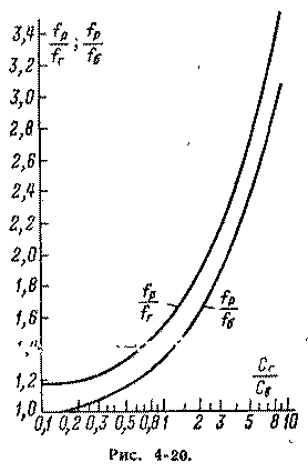
3) against SG / ST using the nomogram in Fig. 4-20 define the relationship fР / fГ, provide a box of volume V. the Frequency of mechanical resonance of the speaker in the acoustic screen can be taken from the table. 4-11.
If you want with the existing speaker to get the sound system in the form of a closed box with a resonant frequency fР , the required volume of the case is determined in the following order:
1) get the value of the resonant frequency of the loudspeaker fГ in the acoustic screen from the table. 4-11;
2) determine the flexibility of the suspensions of the movable system of the loudspeaker SG;
3) having a desired attitude fР / fГ , determined according to the schedule in Fig. 4-20 corresponding ratio SG/ST and find the required flexibility of the air volume of DM in a closed case;
4) calculate the required volume of air inside the box in cubic metres by the formula
Total internal volume of the case receive, adding to the computed value V the volume of the loudspeaker.
If the value fГ unknown or difficult to determine in the acoustic screen is large enough, it is possible to measure the mechanical resonance frequency of the loudspeaker fБ , without screen and in the calculation of the curve to use fР / fБ in Fig. 4-20.
The above calculation is valid only for frequencies f<;40/L ( L is the depth of the case in metres). In this regard, the back side of the cone loudspeaker in a closed case to protect against inner walls of the reflected sound waves corresponding to a higher frequency, cover these walls with sound-absorbing material .
The dimensions of the closed case can be reduced by filling it with glass wool or other similar material. Such filling is equivalent to increasing the volume of the box is 40%.

If calculation frequency /R is sufficiently low, then the speaker needs to have a Q of about 1. If the frequency fР unacceptably high, good results are obtained by reduction of q to Q values of about 0.1; of course, the necessary lifting of the lower frequencies in the amplifier by about 6 dB/octave from the frequency

The calculation of the phase inverter
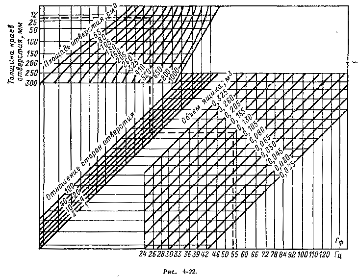
The phase inverter is the case 1 (Fig. 4-21) with an additional hole 3, located near the fortified on the same wall loudspeaker 2 and having a size generally equal to the area of the diffuser. Having a phase depth of the hole with respect to its sides, by calculating the effective area of the diffuser (which determines the size of the hole) and taking the resonance frequency of the bass reflex fФ = fГ, the nomogram in Fig. 4-22 possible to determine the case.
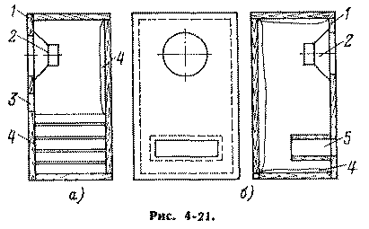
The distance from the end of the tunnel to the back of the box should not be less dГ /2.
Frequency fФ the phase inverter can be considered as an acoustic transformer, improves the agreement of the speaker with an air load. Although the acoustic power delivered from the front side of the diffuser is reduced at this frequency, the total acoustic power may increase significantly. However, significantly reduced harmonic distortion and increases the rated power of the speaker due to the decrease of the amplitude of the displacement diffuser..
The a phase depth of the hole can vary from the wall thickness of the shell (Fig. 4-21, a) to a value of approximately $ 30 / fФ when using tunnel 5 (Fig. 4-21, b). A significant length of tunnel allows you to apply a small box.
At frequencies below fФ reaction to the flexibility of the air volume increases and forms a rigid connection between the mass of air in the hole and the mass of the moving system of the speaker. Air mass, thus, added to the mass of the moving system and the flexibility of the suspension forms a mechanical circuit with a resonant frequency f1 < fФ . When the diffuser on this frequency moves forward, the air in the hole moves back (and Vice versa) and the efficiency of radiation is negligible.
At frequencies above fФ , soprotivleniem air hole becomes high and the bass-reflex can be seen as a completely closed case. The stiffness of the air volume is added to the stiffness of the suspensions and together with the mass of the moving system forms a circuit with a resonant frequency f2 > fФ . Radiation phase-hole at the frequency f2 is very small.
Total electrical impedance of the loudspeaker RГ in the phase inverter usually has two peaks (solid curve in Fig. 4-23) at frequencies f1 and f2 , located on either side of the resonance frequency of the loudspeaker in a flat acoustic screen fГ (dashed line in Fig. 4-23, where R is the resistance of the coil loudspeaker DC).
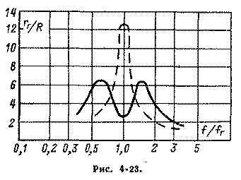
The peaks in the impedance of the loudspeaker in a bass-reflex significantly below the peak of the speaker in the acoustic screen, however, the corresponding values Q1 and Q2 above Qr speaker in the acoustic screen. This disadvantage is particularly apparent at the frequency f1 , as the increasing speed of the diffuser increases harmonic distortion, the visibility of which contributes to the lack of the useful radiation at this frequency. This phenomenon can be combated by limiting the output power of the amplifier at frequencies close to f1 .
If it is desirable that the frequency response of the loudspeaker in a bass-reflex was horizontal in the lower part of the operating range of frequencies, starting from g, it is necessary to satisfy the condition q Mr. = 0,6.
If you increase the value of q Mr. Qg increases, and the value QФ decreases and this causes uneven frequency characteristic tanishiki. If you reduce the Qr is not possible, it is necessary at least to suppress the peak of the frequency characteristic at the frequency f2 occurs when q Mr. > 0,6 . This is achieved by introducing into the box sound-absorbing material 4 (see Fig. 4-21). Sometimes the entire volume is filled with glass wool. In this case, the area of a phase-holes obtained by the nomogram in Fig. 4-22, should be increased by 2.5 times.
Introduction to the inverter with a large number of absorbent material leads to the release of radiation of lower frequencies, and, if desired, extend the feature in the direction of these frequencies, at least up to fГ , should provide a significant bass boost in the amp.
The bass reflex tuning is achieved by changing orifice area (for example, a plate reinforced so that its rotation changed the size of the hole) or the depth of the tunnel. You must strive to ensure that the frequency interval separating the resonance peaks in the impedance, did not differ significantly from the octave; the amplitude of the peaks were equal; any additional peaks caused by the occurrence of standing waves in the box, were eliminated by adding damping material.
The advantage of the phase inverter in comparison with the closed box of the same volume is to increase the acoustic output of approximately 5 dB in the range from one to two octaves and to reduce harmonic distortion in the frequency range fФ - 2/f with the same acoustic power.
A disadvantage of the phase inverter is a faster reduction of the acoustic power at frequencies below fФ than in a closed box, and setting needed.
Construction cases
In the case where the mounted loudspeaker, on one or several frequency sound range of possible resonance, leading to unpleasant timbre of sound reproduction. This phenomenon manifests itself most strongly in a partially or fully enclosed protective case.
Vibration of the walls promotes the use of materials with a high density. Used for these purposes, the plywood should have a thickness not less than 20 mm gives Good results dry river sand, fall asleep between two thin plywood sheets. Wall, especially the rear and front partially, should be strengthened with wood slats. You can use chipboard.
The damping of the walls of the case
The inner surface of the case 1 (Fig. 4-24) covered with a layer of sound-absorbing material 6 with a thickness of 10 mm (or one of the pairs of parallel surfaces with a layer of double thickness). However, standing waves at low frequencies while not eliminated.
The best result gives the division of the volume of the case one or more sound-absorbing walls 2, for example, made of felt with a thickness of 5-10 mm. Section of the box, which is separated from the speaker by one or more partitions, in this case, demand is very weak acoustic treatment. Vernacularly loudspeaker 4 must be protected against radiation rear diffuser low frequency loudspeaker with several layers of absorbent material, or a metal cap 5. Low frequency loudspeaker 3 is placed at the bottom of the case.
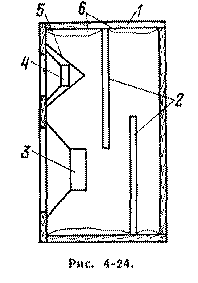
The placement of the loudspeaker
The hole that houses the loudspeaker behaves as a pipe, the length of which is equal to the thickness of the wall or Board. Resonances and antiresonances this pipe, as well as reflections from the edges of the hole cause uneven frequency response. Obvious recommendations: the cutting edges of the holes or attaching the loudspeaker in thinner screen, which is then placed in the wall or screen of a normal thickness.
The shape of a box
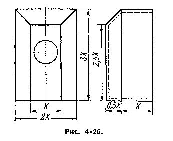
At lower frequencies the loudspeaker emits a spherical wave, and the edges of the box, especially those which constitutes the front wall, form obstacles in the way of sound waves. This causes the curvature of the wave front (diffraction) and secondary radiation from the edges, which leads to interference phenomena, causing the appearance frequency response peaks and dips of up to ± 5 dB. From the point of view of the struggle with the secondary radiation of the perfect shape is a sphere, the worst - cube with the loudspeaker in the center of one of the parties. A rectangular parallelepiped with a loudspeaker placed closer to one of the short sides is preferable to Cuba. However, the best approximation to the ideal gives a rectangular truncated pyramid, raised on a rectangular parallelepiped (Fig. 4-25). Whatever the form, it is desirable that the box had different values of the linear dimensions; none of the linear dimensions was not much more or a lot less than others; the largest size of the box should not exceed 1/4 of the wavelength of the lower frequency operating range.
Decorative fabric should not cause significant loss of acoustic performance. The most suitable fabric made of solid, sturdy (made of cotton or plastic) loosely twisted yarns. The use of fabrics soft and fluffy threads undesirable.
The connection to the group and the phasing of the speakers
Group connection form multiple identical loudspeakers placed close to one another in one of the acoustic screen. The group of speakers has a large area radiation at lower frequencies (which would require using a single loudspeaker significant increase in the size and weight of a mobile system); however, there remain advantages of the individual loudspeaker with a relatively lightweight mobile system-from the point of view of the transitional regime and the treble.
Air resistance radiation of each speaker group increases at lower frequencies in p time (ha) - number of speakers in the group). This would provide a significant gain in acoustic power, if not at the same time increased the square root of n times the mass of cocolamus-gosia air. As a result, when n == 2 -:- 4 acoustic power increases significantly, but still not in I times (with the same electrical power), but further increase in n scoring almost does not.
The increase in the mass of carolblymire air lowers the resonance frequency of each speaker group and therefore extends the operating frequency range, is particularly significant when the big I am.
The most satisfactory connection of the speakers to the group - parallel; then Q system will not differ from q Mr.. If you want the resistance group was equal to the impedance of one speaker, then from the point of view of the best Q groups is better to use a series-parallel connection of the loudspeakers (which must be equal to n2, where n = 1, 2, 3 ...). Any connection of the speakers in the group, they must be properly phased: when connecting the DC source (for example, low-voltage battery) to the input terminals diffusers of all loudspeakers should move in the same direction. The change of the direction of displacement of the cone of the speaker is made by changing the order of inclusion of its input ends.
If the speaker in a closed box meets obstruction - required volume of the case is obtained by calculation unacceptably high, the speakers can be placed in a small acoustic screen or smaller box filled with absorbent material, compensating for the attenuation of radiation at lower frequencies corresponding correction in the amplifier.
The disadvantages of group connections is considerable irregularity of the frequency characteristic and directivity at higher frequencies.
Two - and three-way speaker system
The choice of speakers. The sound quality in class I usually can be obtained by using a broadband loudspeaker, for example GD, GD or GD or dividing a full frequency range corresponding to that class, two lanes. To ensure audio quality to "highest" is found necessary to divide the total range into three bands.
The nominal frequency range of the loudspeaker, intended for playback of one or other of the strip should be wider than this band two octaves when using filters with a slope of 6 dB/octave and one octave when using filters with a slope of 12 dB/octave. A crossover frequency of a two-tiered system usually choose from 400 to 1 200 Hz. In the three-band system low frequency link can work up to 300-600 Hz, mid - to 2,000 - 5,000 Hz.
Near the frequency separation often leads to significant distortions caused by the joint work of the speaker. If the distance from each speaker to the listener unequal, then the frequency response of the system can have a significant disparity-defined phase relations of the incoming signals.
The separation filters. The simplest connection verkhnesaltovo loudspeaker through a capacitor protecting vernacularly loudspeaker overload on the lower frequencies. Such inclusion is used when the main speaker has a wide enough frequency range. The capacitance of the capacitor is calculated by the formula

where fР - crossover frequency, Hz; RP - impedance loudspeaker frequency fР , Ohm.
When properly constructed the filter every speaker needs to work only in the range of frequencies for which it is designed. The losses in the filter bandwidth should be minimal.
Inductance and capacitance of the filter with different cut-off slope, which is defined as the change in attenuation for a frequency change of one octave, are calculated by the following formulas.
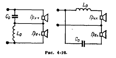
For a slope of 6 dB/octave (filter according to the scheme in Fig. 4-26)
For slope 12dB/octave (filter according to the scheme in Fig. 4-27)
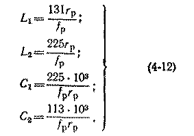
In formulas (4-11) and (4-12) inductance have dimensions of millihenry and capacity - microfarads.
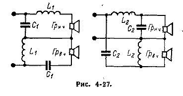
Based on the calculation choose capacitors with the nearest larger standard nominal capacities. To choose capacity possible parallel connection of several capacitors. It is obvious that the deviation of the capacitance obtained from the calculation of the size of the crossover frequency will be' different from the specified one.
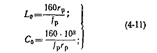
If the desired filter capacity of the order of tens of microfarads and above, it is possible to reduce its size it is advisable to use electrolytic capacitors. Since the last polar, and will work in an AC circuit, at each stage of the filter will have to use two counter enabled capacitor, each of which must have the capacity, possibly closer to calculation. The links of the crossover transformerless transistor amp you can apply one electrolytic capacitor, observing the correct polarity for their inclusion.
Filter for three-way acoustic Assembly (Fig. 4-28) is a combination of two filters discussed above. The first separates the low frequency region from mid-frequency; the latter is then divided by the second filter. Both filters should not have the same steepness of the cut; they should only be calculated for a single resistance.
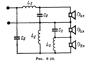
The method of calculation of the separation filters is based on the assumption of equality and active speakers in shared bands. Since the impedance of the loudspeaker at the crossover frequency can have a significant inductive component, in order to avoid frequency distortion in the overlap region should be taken into account when calculating the inductance of the medium and low frequency loudspeakers as part of a filter, i.e. manufacturing coil filter connected in series with the loudspeaker, with less than the calculated inductance the inductance of a speaker.
If the resistance of the speakers in the links of a multi-way system are not equal, you should try to choose an equal resistance links through group connections (valid serial connection verniciatura speakers) .
Parallel connection of two or three verniciatura speaker gives the opportunity to use them in combination with almost any nigedashita loudspeaker. A possible discrepancy in the values of the full resistance of the links of the acoustic system can be eliminated by increasing the input resistance verkhnesaltovo link by using a voltage divider of the resistors.
If two - or three-tier system is used several verniciatura loudspeakers (for example, GD-3), they should be placed in the pouch so that the angle between their axes in a horizontal plane had a value of about 20-30°.
If multiband audio system uses only one vernacularly loudspeaker having an impedance greater than that of the low frequency loudspeaker level, in order to equalize the load resistance of the separation filter in the upper frequencies vernacularly loudspeaker should be bypassed with a resistor of the appropriate resistance.
Stereo speaker system
The two-channel stereo speaker system must be strictly identical. They should be located in accordance with Fig. 4-29, where the optimal area"' the stereo effect is shaded.
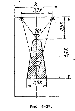
The orientation of the speakers depends on their directional characteristics and must be determined experimentally. The axes of the speakers should not intersect at the location of the audience.
Publication: N. Bolshakov, rf.atnn.ru


