


")

The proposed calculation method based on simple measurements performed with the well-defined instance of a loudspeaker mounted in bass reflex and acoustic on demograficheskim determining the size of the latter.
In the first place, guided by Fig. 1 and table, you need to make a "standard volume"- sealed plywood box, all joints which prevent air leaks carefully fitted, glued and coated with clay.
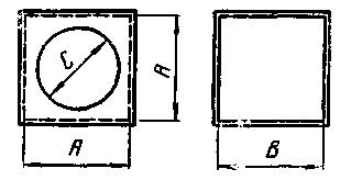
Fig. 1
The diameter of the diffuser
loudspeaker, mm
Dimensions,mm
And
In
With
200
255
220
170
250
360
220
220
300
360
220
270
375
510
220
335
Next, measure the natural frequency of resonance of the loudspeaker in free space. To do this, it hung in the air away from large items (furniture, walls, ceiling). The measurement scheme is shown in Fig. 2.
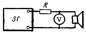
Fig. 2
Here ZG - graded sound generator, V - tube voltmeter AC and L - resistor 100-1000 Ohm (for large values of the resistance measurement is more accurate).
Rotate tuning frequency of the sound generator in the range of 15-20 to 200-250 Hz, achieve the maximum deflection of the voltmeter. The frequency at which the maximum deviation is the resonance frequency of the loudspeaker in free space FB.
The next step is to determine the resonant frequency of the loudspeaker FB in production on "standard volume". To do this, the speaker put the diffuser on the hole "standard volume" and gently pressed in order to avoid air leakage at the joint surfaces. Method for determining the resonance frequency of the former, but in this case it will be 2-4 times higher.
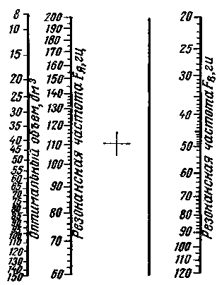
Fig. 3
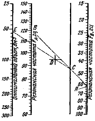
Fig. 4
Knowing these two frequencies, using nomograms are the dimensions of the phase inverter. Depending on the diameter of the cone of the loudspeaker choose the nomogram shown in Fig. 3 (diameter 200 mm), in Fig. 4 (diameter 250 and 300 mm) or in Fig. 5 (375 mm diameter). The selected nomogram determine the volume of the port, which connects with a straight line of pixels corresponding to the found frequencies on the axes "Resonant frequency
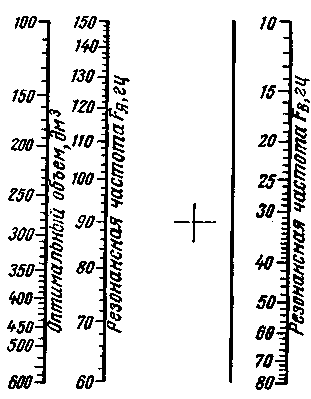
Fig. 5
FB (see Fig. 4 point a) and Resonance frequency Fi (point b). Mark the point of intersection With the auxiliary axle and from there lead to the second straight line through the point D from the axis "optimal amount". The value corresponding to the new intersection point E, and is the required volume.
If there are any special considerations for designing a special box configuration, the internal calculation of its size at a given volume can be made by the nomogram shown in Fig. 6. The width of the phase inverter is equal to 1.4 height, and height - 1,4 depth. Use of the nomogram is not difficult: perform a direct line between the extreme axles, which are inscribed with' the magnitude of the volumes. The point of intersection of the line with the axes A, b, C will determine the width, height and depth of the box. The diameter of the cutout for the speaker is taken equal to the size specified in the table.
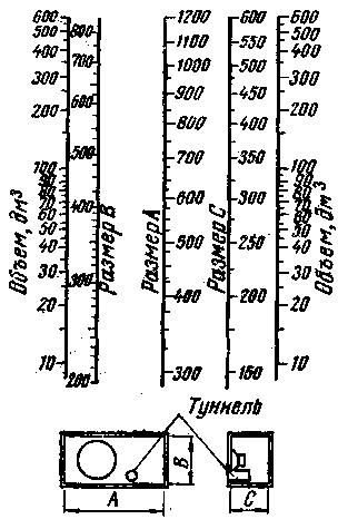
Fig. 6
Further, having a diameter of the tunnel, it is necessary to determine its length and test fit it in the box bass reflex. The length of the tunnel is found from the graphs shown tion in Fig. 7, for the three inner diameters: graphics - for diameter 50 mm to 75 mm in diameter and of a diameter of 120 mm. Selecting the appropriate graphs, frequency FB and the volume of the phase inverter as defined previously, find the length of the tunnel (the example in Fig. 7). It should be 35-40 mm less than the internal depth of the box. If this does not work, you have to change the configuration of the box, keeping its volume, or take the Other diameter of the tunnel.
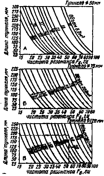
Fig. 7
The phase inverter are made from plywood with a thickness of about 30 mm. If this is not thick plywood, it is possible to increase the rigidity necessary to glue inside the box diagonally or crosswise bars size H mm Drawer assemble with screws and glue and all seams are sealed. The rear wall is recommended to be fixed with screws (five pieces per side) with a felt strip. The tunnel is made from thick-walled cardboard tube.
Making a bass reflex port and insert the speaker, start to damping. For this loudspeaker is recommended to completely cover the back side with a layer of glass wool with a thickness of 25-50 mm, attaching it to the Board around DiffuseMaterial the ring, screwed by screws or screws.
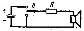
Fig. 8
Sufficient damping is tested with the scheme shown in Fig. 8. The resistance of the resistor I is taken approximately 0,5 Ohm. If known, the damping coefficient To the amplifier will operate the unit, and the resistance of the voice coil of the loudspeaker AC r, it can be determined from the formula R=r/K ohms. Translate the switch from one position to another, listen to the clicks in the speaker. If it is quite clear I'm not a "mumbling" or "ringing", it means that the damping is sufficient. Make final decision after listening to orchestral music with pronounced bass and the top cats.
Author: Yuri Lyubimov; Publication: N. Bolshakov, rf.atnn.ru