To reduce intermodulation distortion in the reproduction loudspeakers Hi-Fi systems are in the range of woofer, midrange and tweeter drivers. They are connected to the outputs of the amplifiers through a separation filters, which are combinations of LC filters of the lower and upper frequencies.
Below is a method of calculating three-band dividing filter according to the most common scheme.
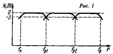
Frequency response crossover three-way loudspeaker in the General form shown in Fig. 1. Here N is the relative level of the voltage on the voice coil heads: FH and FB - lower and upper cut-off frequency reproduced by the loudspeaker of the strip; fр1 and fр2 - frequency section.

In the ideal case, the output power at frequencies section shall be distributed equally between the two heads. This condition is satisfied, if the frequency of the section relative to the voltage level supplied to the corresponding head is reduced by 3 dB compared with the level in the middle part of its operational frequency band.
The crossover frequency should choose out of the region of greatest sensitivity of the ear (1... 3 kHz). Failure of this condition, due to the phase difference of the vibrations emitted by the two heads on a frequency at the same time, you may notice the "split" sound. The first section frequency usually lies in the frequency range 400... 800 Hz, and the second 4... 6 kHz. Thus low-frequency head is able to reproduce frequencies in the range FH...fp1. mid - range fp1... fр2 and high-frequency - range fр2...FB.
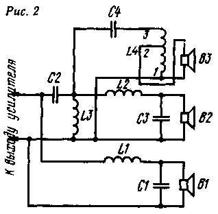
One of the common options electrical schematic diagrams of the three-way loudspeaker is shown in Fig. 2. Here B1 is the low-frequency dynamic head, connected to the amplifier output through a low pass filter L1C1; B2 - bass head, connected to the amplifier output through a band pass filter formed by the high-pass filters C2L3 and lower frequencies L2C3. At high frequency head B3 signal is fed through a high-pass filter C2L3 and C4L4.

The calculation of the capacitors and inductances of coils produce on the basis of the nominal resistance of the heads of the loudspeaker. Since the nominal resistance of the heads and the nominal capacitance of the capacitors form a series of discrete values, and the crossover frequency can vary within wide limits, the calculation it is convenient to make in that order. Having a nominal impedance heads, choose the capacitance of the capacitors from a number nominal capacity (or the aggregate capacity of multiple capacitors of this series) such that the resulting frequency section fall into the above frequency intervals.
In the separation filters typically use metalloboranes types of capacitors MBGO, MBGP and MBM with a tolerance of the nominal capacity of not more than ± 10%. Most suitable for use in the filters of the part types of capacitors are given in table. 1.
The type of capacitor
Capacitance, µf
MBM
MBGO, MWGP
MBGP
MBGO
0,6
1; 2; 4; 10
15; 26
20; 30
The capacitance of the filter capacitors C1...C4 for the various resistances heads and the corresponding frequencies are given in section table. 2.
ZG,0m
4.0
4.5
5.0
6.5
8.0
12,5
15
C1,C2, IFF
40
30
30
20
20
15
fp1, Hz
700
840
790
580
700
-
520
C3,C4,
UF
5
5
4
4
3
2
1 .5
fр2,Hz
5.8
5.2
5.
4,4
4.8
4,6
5.4
It is easy to see that all the values of the capacitances can be either directly taken from the nominal range of capacities. or the parallel connection of two capacitors (see tab. 1).
After the capacitance of the capacitors is selected, determine the inductance of the coils in millihenry by the formulas:

In both formulas: ZG-ohms; fp1, fр2 - in Hertz.
Since the impedance head is a frequency-dependent value for the calculation usually takes specified in the passport of the head nominal impedance of ZG, it corresponds to the minimum value of the impedance head in the frequency range above the frequency of the main resonance to upper frequency limit of the operating band. It should be borne in mind that the actual nominal resistance of various samples heads of the same type may differ from the certified value ±20%.
In some cases, hams have to use as high frequency heads available dynamic heads with a nominal impedance different from the nominal impedance low frequency and high frequency heads. The harmonization of resistance carried out by connecting the high frequency v3 head and the capacitor C4 to the various terminals of the coil L4 (Fig. 2), i.e. this coil filter simultaneously plays the role of matching autotransformer. Coils can be wound on a round wooden, plastic or cardboard frames with side cheeks of Micarta. Lower cheek should make a square; so it can be conveniently secured to the base - laminated bakelite Board, on which are fixed capacitors and coils. Charges attached with screws to the bottom of a box loudspeaker. To avoid additional nonlinear distortion of the coil must be performed without the cores made of magnetic materials.
An example of the calculation of the filter
As low-frequency driver speaker uses a dynamic head GD-2, nominal impedance of ZG which=8 Ohms. as a mid - GD-4 with the same value of ZG and as high-frequency - DDG-15, for which ZG=6.5 Ohm. According to table. 2 when ZG=8 Ohms and capacitance C1=C2=20 µf fp1=700 Hz, and when the capacitance C3=C4=3 μf fр2=4,8 kHz. In the filter capacitors MBGO with standard containers (C3 and C4 comprise two capacitors).
In the above formula, we get: L1=L3=2,56 mg; L2=L4=0.375 mg (autotransformer L4 is the value of inductance between pins 1-3).
The transformation ratio of the autotransformer

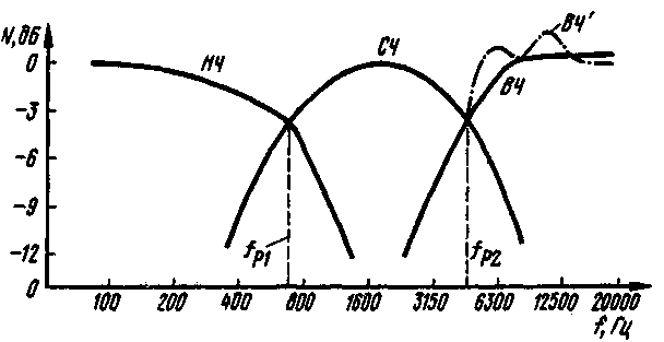
In Fig. 3 shows the dependence of the voltage on the voice coil heads versus frequency for three-way systems corresponding to the calculation example. Amplitude-frequency characteristics of the low-frequency, mid-frequency and high-frequency regions of the filter respectively designated LF, MF and HF. At frequencies section the attenuation of the filter is equal to 3.5 dB (at the recommended 3 dB attenuation).

Fig. 3
The variance explained by the full difference of resistance of the heads and of the capacitors from the specified nominal values and the inductances of the coils from the calculation. The slope of the curves LF and MF is 9 dB per octave curve and RF - 11 dB per octave. Curve HF corresponds to the inconsistent inclusion of loudspeaker 1 GM-3 (points 1-3). As can be seen, in this case, the filter introduces additional frequency distortions.
In the method of calculation, it is assumed that average sound pressure at the same the electric power supplied to all of the heads has roughly the same value. Veli same sound pressure created by any head, considerably larger, to compensate for the frequency characteristics of the loudspeaker sound pressure this head it is recommended to connect to the filter via a voltage divider, the input resistance of which should be adopted when calculating the nominal resistance of the heads.
Author: E. Frolov, Moscow; Publication: N. Bolshakov, rf.atnn.ru


