To listen to television broadcasts on the headphones, not necessarily to pull away from the TV wire communication line. Help out the proposed wireless system (it was described in article V. Gushchina, I. Postca "Broadcast on the IR rays" in "Radio", 1986, No. 1, p. 27) that uses infrared (And To) the radiation of the LEDs. In other words, the TV is set low power radio transmitter that emits a modulated audio frequency infrared waves, and is attached to the headphones receiver catching these waves and allocating them the modulating signal.
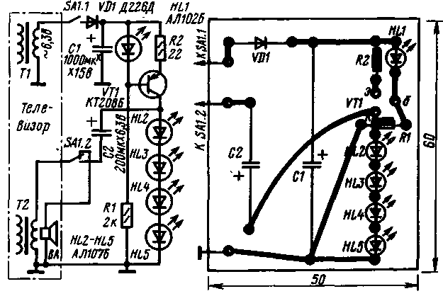
Scheme prefix-transmitter to the TV shown in figure 1. To power the transmitter used half-wave rectifier diode VD1, the AC voltage which is supplied with filament winding of the power transformer (T1) of the TV through the contacts SA1.1 switch the operation mode. The rectified voltage is smoothed oxide capacitor C1 and supplied to the current regulator, performed on the transistor VT1. As a supporting element in the stabilizer used led HL1, which simultaneously serves as the indicator switch on the transmitter.

figure 1
The current stabilizer connected chain of four series-connected diodes (HL2-HL5) - sources of radiation in the infrared range. The current through them is chosen equal to 50 mA, with the diodes emit about half the maximum power.
The audio frequency voltage is supplied to the LEDs from the secondary winding of the transformer (T2) of the amplifier 3H through the capacitor C2. Thus in time with the oscillations 3H changes emitted by the LEDs power. So is the modulation of the infrared radiation.
The transmitter starts to work, when the movable contacts of the switch are in the bottom on the diagram position. Dynamic head of TV in this case off.
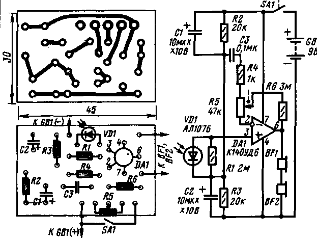
The receiver circuit is shown in figure 2. In it - one led VD1, perceiving IR radiation. It is connected to the amplifier 3H, assembled by operational amplifier DA1. From the amplifier output audio signal is supplied to the blasting BF1 and BF2 headphones that are connected in series. The sound volume adjust variable resistor R5. It feeds the receiver from battery GB1 ("Crown") .

figure 2
The transmitter can be used transistor CT with an alphabetical index A-M, as well as any series transistors MP, MP. Rectifier diode - any of the series D226, D7, CD; led 1 HL - any of a series of AL 102; the remaining LEDs - any of a series of AL 107. Oxide capacitors - C50-24 or similar, resistors - MLT-0,125, MLT-0,25. Switch (mounted on the rear of the TV) - MT, P2K.
In the receiver you can apply operational amplifiers COD, COD, any led from the AL 107, capacitors K53-1, K50-6 (C1, C2), KLS, KM (C3), fixed resistors MLT-0,125, MLT-0,25, variable resistor - CP3-3V (he with the power switch SA1), headphones TONE-1, TONE-2, TAG-1 (in any case, the fuses are connected in-series) .
Details of the transmitter and receiver are mounted on printed circuit boards. Boards installed in the buildings of suitable dimensions. In front of the LEDs in the front walls of the drill hole. The LEDs of the transmitter should be placed horizontally and be directed towards the viewer. A similar provision should take the light emitting diode, but is directed toward the transmitter.
The transmitter power and receiver sensitivity is sufficient for good reception anywhere in the relatively large room. Moreover, the receiver confidently takes the direct IR radiation from the LEDs of the transmitter, but also reflected from the ceiling, walls and other objects. Since the emitting and receiving LEDs have a narrow focus, for uniform desirable emitting diodes oriented in different directions, and one or two to send to the ceiling or wall. Then regardless of the head position, the volume will be the same.
For a small room the number of emitting LEDs can be cut and experimentally to pick up as much as needed for reliable reception. The transmitter circuit is not changed.
The transmitter can be used with transistor TVs that have no filament winding. In this case, the modulation scheme remains the same, only the capacitance of the capacitor C2 is increased to 470 μf (rated voltage 15 V) and in series with the capacitor include a constant resistor-resistance of 0.5 to 2 ohms, and emitting LEDs connected to a power source through the quenching resistor with the same resistance, so that when the current 40...50 mA on the four LEDs were provided with a voltage drop of about 5.2 In (1.3 In each). Depending on the incident on the resistor voltage determine the desired nominal power dissipation of the resistor. Details of the current stabilizer with this power, of course, is not required.
If the transmitter is difficult to connect to the rectifier TV, it is fed from a separate stable block with an output voltage of 9...15 V at a current of not less than 50 mA.
It should be added that such a communication system can be equipped not only television, but also other devices such as a radio, tape recorder.
(RADIO No. 8, 1986, p. 33)


