Ham radio operators engaged an independent manufacturer of loudspeakers-inverters (hereinafter referred to as simply port) is often confronted with the fact that repeated their designs do not provide are listed in the descriptions of the technical characteristics. It happens because of the significant variation * process variation subwoofer, so everyone made the speaker you want to adjust.
When configuring the inverters hams are usually the same method as in their calculation [1, 2]. The result is unaccounted for in the actual design of acoustic losses, the difference between the equivalent and the physical volume of the box and a number of other affecting the accuracy of the adjustment factors. The proposed adjustment methodology takes into account these factors, so its accuracy is much higher.
Any phase inverter is reduced, as is known, to find a certain combination of values of the frequency settings fф and output resistance of the amplifier Rвых which provides a smooth frequency response radiation at low audio frequencies. To find these values, using dependency that exists between the parameters of the bass reflex and sealed box. If the bass reflex design with a smooth response curve to close the opening of the tunnel, complete quality system head - sealed box will be equal to 0.6, and the resonant frequency of the head in this box fр will be related to the tuning frequency of the bass reflex dependence fф=... 0,65 0,61 fр. The coefficient of proportionality of such values depends on the ratio of the equivalent volume of the head to the useful volume of the box, and if it is equal to 0.63, the error in determining the frequency fф will not exceed 5 % in any relationship of these volumes that occur in real structures.
Tuning bass reflex should begin with determining the optimal number to be placed in it a sound-absorbing material. For this purpose, closing the tunnel opening (for example, plywood circle, blurry at the edges of clay), choose the material, in which the frequency fр minimum. Then, securing the absorbing material on the walls of the box, measure the resonant frequency of the system head - sealed box and, using the ratio fф=0,63 fр, determine the tuning frequency of the port, and then the length of the tunnel:

where V is the free volume of the box in litres bass reflex, a S is the area of the bore of the bass reflex tunnel in sq cm.
Usually an equivalent amount of acoustic design when placing it in the optimum quantity of sound-absorbing material is more geometric, so the length of the tunnel when you configure the phase inverter is necessary to reduce. To determine the adjusted value 1' in the above formula, substitute the value of the tuning frequency of the port, resulting in the length of the tunnel 1 and are equivalent volume of the clearance Vэ. Then, replacing in the same formula V Vэ calculate the updated value of the length of the tunnel 1'.
The output impedance of the amplifier Rвых can be found on the basis of the conditions under which the quality system amplifier - sealed box assumes a value of 0.6, however, it is preferable to determine the amount Rвых of the conditions under which the quality system amplifier - drawer phase inverter takes the optimal value of 1 (in this case, the simplified method of tuning amplifier and appear to be accounted for losses arising in the tunnel of the inverter).

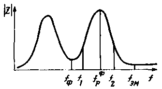
The quality factor of the system head - box-vented determine the method adopted for systems head - sealed box [1,2], but all the necessary measurements carried out near the frequency of the high frequency resonance frequency response input impedance of the loudspeaker fр (see figure). To improve the accuracy of subsequent calculations, the frequency response of the input impedance of the loudspeaker should be measured from the side of the connector to connect it to the amplifier. In this case, it is considered the impact resistance of the connecting wires and coil crossover on the speaker options.
Calculating the acoustic quality factor [3]

where M -- - frequency voltage fр, IEM - frequency voltage Electromechanical resonance fэм, f1 and f2 of the cutoff frequency on voltage level U1,2=root(UрUэм), find electrical and overall quality factor of the system:

if you found value Qп differs from unity by no more than 10 %, then the response of the phase inverter will be quite smooth when working together with almost any transistor amplifier with low output impedance. If Qп>1,1 (this is the case in Amateur practice the most common), to work with bass reflex should use the amplifier with a negative output resistance. To get a smooth response curve of the loudspeaker, you must configure a feedback circuit that generates a negative output resistance amplifier [4]. For this pre-determine the damping coefficient CD=Qп/Qп.wholesale, which shows how many times you need to reduce the quality factor of the system head - drawer-phase inverter to obtain the optimal damping. Since the optimal damping bass reflex involves Qп.opt=1, KD=Qп. Further, by connecting a loudspeaker to the amplifier and output at the last beep frequency fэм balance the bridge, the feedback circuit and measure the voltage at the amplifier output. Then, rebuilding the generator frequency fр and changing the transmission factor of the feedback network, we achieve a decrease of the output voltage of the amplifier in CD time. In this setting, it is set then the value of the output resistance of the amplifier, whereby is obtained a smooth frequency response of the loudspeaker at low frequencies.
When calculating the power amplifier to the desired output impedance is desirable to determine in advance. It is calculated by the formula

The procedure given above without any changes applicable to configure the speakers have dual or multiple heads of the same type.
Literature
Author: Vladimir Zhbanov, Kovrov, Vladimir region; Publication: N. Bolshakov, rf.atnn.ru


