When the sound of television broadcasts interfere with others, you have to use headphones that are included instead of the dynamic head of the TV. There is a more radical way is to connect to the TV instead of the head frame of the wire, which is extended along the baseboard of the room, and broadcasts in the tiny receiver signals CC, mounted on the headphones.
To get rid of the wires connected to the TV, offer another option is the transmission of signals 3H ether. By the way, this option will be silent listening to the radio, tape recorder, or any other sound source.
The best way to implement the proposed system in the range УSW where it is easy to make Micropower УSW transmitter, and its signals are received by using existing small УSW receiver or player with УSW range.

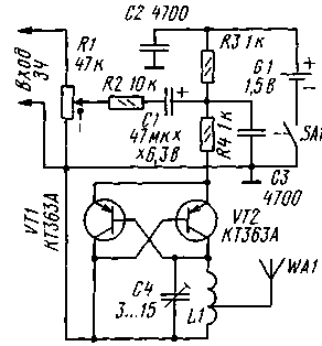
Scheme Micropower УSW transmitter with frequency modulation is shown in figure 1. It is an asymmetrical multivibrator with customization circuit L1C4. This scheme is well known to radio Amateurs involved in the construction of the transmitter-receiver apparatus, it is used in the design of oscillator smooth range (GPA).
The distinguishing feature of the generators on the basis of this scheme is the ability to operate at high frequencies with very small currents and voltages.
As the power source of the transmitter uses a single galvanic cell voltage of 1.5 V. the Constant current through the transistors is set by resistors R3, R4. The change of this current leads to a small change in the frequency of the generated oscillations, therefore, to obtain frequency modulation in dakotadome circuit with resistor R1 through the capacitor C1 and the resistor R2 serves modulating voltage 3H from the signal source. The magnitude of deviation adjust variable resistor R1, and since it is combined with the switch SA1, they also turn off the transmitter.
The transmitter power is small - less than 1 mW, so any radio interference neighbors it will not create, at the same time, this is sufficient for reliable reception of its signal in the room. At a voltage of 1.5 V current consumption is 0.42 mA, which indicates the high efficiency and ability to operate from a single battery for a long time. A normal value of the deviation is obtained by a signal of 3H with an amplitude of 100 mV, input impedance is 10 ohms, so connect the transmitter to the line out port of a TV, tape recorder, radio, etc.
The efficiency of the transmitter is maintained when reducing the supply voltage to 0.8...0.9 V, i.e. almost to exhaustion of the battery, and the consumed and the current is 0.07...0.1 mA. The antenna can be cut copper wire with a diameter of about 1 mm and a length of 20 cm to 1 m. the longer the antenna, the greater the coverage of the signal transmitter.
All parts of the device are placed on the PCB from double-sided foil fiberglass. Details establish on the one hand, and the second left metallized and connected to the common wire on the circuit Board in a few places. On the same side of the fixed battery.
The device may be operated variable resistor SDR-4, SDR-3 with a power switch, fixed resistors - MLT, C2-33, the oxide capacitor - K50, K53, trimmer - KT-25, rest km, KLS, KD. For the range УSW-2 (88... 108 MHz) coil L1 contains seven turns of wire sew-2 0,8 wound on the mandrel with a diameter of 3.5 mm with a branch of the middle.
Adjust transmitter as follows. First, select the range in which it will work, it depends on the receiver. Then the receiver is configured on the part of its range, the most free from the broadcast stations and interference. The transmitter is connected to the line out of the tape recorder or a TV and a capacitor C4 tune it to the frequency of the receiver. Resistor R1 sets the most appropriate frequency deviation, which provided the normal volume and minimum distortion. If the volume will not be enough even at upper circuit on the position of the slider of the resistor R1, it is necessary to reduce the resistance of resistor R2.
Then check the coverage area and if it is low, increase the length of the antenna to 0.7 m.
The transmitter is placed in the housing (plastic) of suitable dimensions, and to connect to a TV, tape recorder or other signal source use screened cable with the appropriate connector.
If small УSW receiver you have, it is easily done using the domestic circuit CHA, CHA or their imported counterparts. Some examples of such receivers have been described in [1-3].
LITERATURE
1. Gerasimov N. Dual band УSW receiver. Radio, 1994, No. 8, pp. 6-8.
2. Makarov D. УSW receiver-pack of "MARLBORO". Radio, 1995, No. 10, pp. 41-43.
3. Semenov B. Simple УSW receiver. Radio, 1996, No. 10, pp. 22,23.
I. NECHAEV, Kursk
RADIO No. 10, 1998


