The most widespread foreign radio Amateurs got two - and three-way speaker system. Often done to further improve efficiency at lower frequencies the loudspeaker housing supply vented. I use other techniques to improve the performance of loudspeakers with two or three bands of frequency division of the signal.
Two-way loudspeaker with the annular inverter.
Usually the hole of the inverter has a rectangular shape and is placed slightly below the hole low-frequency drivers. Because the bass reflex design enhances the sound only at lower frequencies, where the orientation of the radiation is virtually absent, for normal operation of the inverter is irrelevant to the location of the holes, as well as its shape. The main thing is that its area was approximately equal to half the area of the diffuser.
Given the above was the original design of two-way loudspeaker with the annular hole of the inverter, placed on the back wall. The design of this speaker can be understood by the sketch shown in Fig.1.
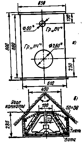
Fig.1
The first feature of loudspeaker design - slit opening width of 26 mm and a length of 860 mm, i.e. the entire length of the rear wall. The second feature - prismatic hull shape: the width of the front panel 610mm, rear - 190 mm lower and upper wall are rectangular dimensions h mm with two truncated corners. This is done to facilitate the placement of the speaker on the floor, in a corner of the room. Thus, two goals are achieved. First, the loudspeaker is placed in the place of the room where it does not interfere. Secondly, there is an additional bass boost on several decibels by reflection of the signal from the two side walls and floor of the room.
The body of the speaker is made from plywood or chipboard thickness of about 20 mm can be fitted to the side braces decorative cloth with the cross-section 90h50 mm - made of pine. The junction of the side walls with top and bottom walls strengthen rectangular plates with a cross-section of 40 x 40 mm, made from Sony. To eliminate the effect of reflection of the signal on the medium and higher frequencies are placed inside the housing quilted layer of natural or mineral wool insulation with a minimum thickness of 50 mm. Such coverage shall be performed on the entire inner surface of the housing.
By repeating designs can use a low frequency head type GD-'2 and the high frequency head type GD-31 and fit the size of the holes on the front panel with the size of diffusers domestic heads. This combination of heads loudspeaker is able to effectively reproduce the signals in the frequency range from 40 Hz to 16 kHz. Input power of the broadband signal can reach 6-8 watts. Crossover network shall have a crossover frequency of about 3 kHz.
In Fig. 2A shows a schematic diagram of the crossover to work with low-frequency head impedance of 8 Ohms and a high-frequency head resistance of 6.5 Ohms. In this case, the resistor R1 is required for alignment of the load resistance high and low frequency outputs of the filter. If the use of domestic high-frequency head at 8 Ohms, resistor R1 should be deleted.
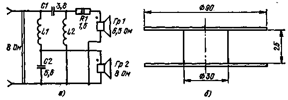
Fig.2
In the manufacture of coils can be used cardboard frames the measurements given in Fig. 41,6. In this case, the coil L1 must contain 100 loops, L2 - 120 turns of wire brand sew-3 with a diameter of 0.9 to 1.1 mm, the Required capacitance of the capacitors C1 and C2 can be obtained by connecting in parallel several capacitors type MBM 160 In with capacities of 1.0, 0.5 and 0.1 μf.
Loudspeaker with reverse exponential horn
Currently among Amateurs and professionals are very popular so-called compact speaker system, abbreviated MAC. Small in size, easy to handle, with a broad band of frequency, they are becoming more widespread. However, they have several disadvantages. The most significant is the relatively small impact in the whole frequency band. For normal operation these speakers require input power of about 10 W or more, whereas for loudspeakers conventional type is 2-3 times less. This disadvantage to some extent offset by increased power of modern low-frequency amplifiers.
The PA MAC has another drawback, due to the specific nonlinear distortion generated by the diffuser. The fact that these speakers use a special low-frequency drivers with a very light suspension of the diffuser. Due to this self-resonant frequency of heads is very low and reaches 10-16 Hz. When installing the head to the body with good sealing its resonance frequency is increased by 2-3 times, reaching required for high-quality sound reproduction of a value equal to 20-45 Hz. Damping diffusers such heads is due to the elasticity of air contained in the interior of the speaker enclosure. The diffuser works like a compressor piston, alternately compressing and expanding the air inside the case. For this reason, low-frequency drivers with easy suspension is called compression or heads with an air suspension of the diffuser.
The reason for the additional nonlinear distortion generated by low-frequency MAC heads, is that the front and back surfaces of the diffuser of these heads have different acoustic impedance. The front surface is in contact with a lot of open space, and a back surface with air, closed in a sealed enclosure of the loudspeaker. Obviously, to address additional specific harmonic distortion subwoofer is necessary to equalize or at least closer to the acoustic resistance of both surfaces of the diffuser.
In one of the magazines had published a brief description of the two-way compact loudspeaker, which significantly weakened the nonlinear distortions of the specified type. When external dimensions HH mm weight 4.9 kg loudspeaker provides effective sound reproduction in the frequency range from 60 Hz to 16 kHz at nominal input power of 10 watts.
The essence of the improvement is to use a reverse exponential horn as an additional acoustic loading for low-frequency drivers. The mouthpiece perform in the body of the front panel of the loudspeaker with a thickness of 20 mm, as shown in Fig.3,and. Front view of the front side shown in Fig.3,b. The inner surface of the speaker enclosure is coated with a layer of cotton wool thickness of about 50 mm, and the magnetic system of the head is additionally drawn in wooden prop, inserted between the rear wall and a magnetic system. The body of the speaker is sealed by microclean, which coat the inside of all joints and connections. Front panel the front side covered with a thin radiomenu, the case itself is pasted over imitating film or they veneer valuable breeds of a tree.
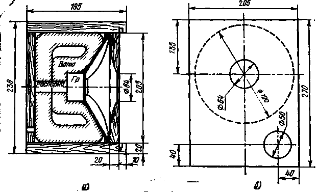
Fig.3
By repeating structures can be used low-frequency compression head type GD-5 and high-frequency head DDG-31. With this structure, it is recommended to use the crossover with a crossover frequency of about 3 kHz.
However, head type GD-31 has a smaller size than the high-frequency head, used by the author of the design. This will require some tweaking of the front panel. But you can do without alterations if you use high-frequency head type 2GD-36.
The use of head type 2GD-36 allows you to effectively extend the streak of reproduced frequencies up to 18-20 kHz. However, there is one feature. Some samples of the heads of this type have a relatively high incidence of low-frequency - about b-6 kHz. In this regard, you may want to change the crossover frequency from 3 to 6 kHz. It's enough to reduce the number of turns of the coils L1 and L2 of the filter according to the scheme of Fig.2 to 70 and 90, respectively, and to decrease the capacitance of the capacitors C1 and C2 is twice
Loudspeaker with extended pattern
Observations have shown that broadband and multiband loudspeakers, which disclose customer diffusers are located in one, usually the frontal plane, have one drawback, due to the narrowness of the beam of radiation. Especially noticeable directionality in the horizontal plane. This narrows the area of existence of the stereo effect, reduces the reproduction of the higher frequencies of the signal.
To combat this drawback apply various means, including the inclusion of additional loudspeakers placed in a certain way relative to the main speakers, making separate medium and high frequency heads, mixing signals of lower frequencies of the stereo system into a single mono signal, etc., Amateur radio practice shows that increasing the number of loudspeakers clutter the living room, leads to an increase in the number of connecting wires. Therefore, a more appropriate is to put the speakers, which would possess a wide beamwidth in the horizontal plane and wouldn't occupy much space.
In Fig. 4,and shows the thumbnails of the speaker enclosure, as in Fig. 4 b is a schematic diagram of its crossover. As can be seen from the figure, the speaker has a pair of heads low and high frequencies connected in parallel. High frequency heads included through simple separation filter consisting of capacitor C1 and resistors R1 and R2.
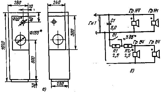
Fig.4
According to the description of the design, low-frequency drivers are designed for 15 watts, high frequency of 10 watts each. Thus, the loudspeaker can be used for collaboration with ULF to 30 watts. The high-frequency power head on almost no influence due to the relatively high crossover frequency bands equal to approximately 6 kHz.
The main advantage of the loudspeaker is a broad radiation pattern in the horizontal plane, component 270° at frequencies up to 12 kHz. This is achieved, as seen in Fig. 4,and, placing pairs of heads high and low frequency in mutually perpendicular planes, and such placement of the four heads does not increase the cross section of the speaker enclosure.
A feature of the filter (Fig. 4,b) is the presence of an additional resistor R1, the closing of the contacts B1. When you open contacts, the frequency response of the loudspeaker is uniform throughout .band frequency (60Hz in kg). With the closure of the contacts results in an additional rise in the effects of higher frequencies (7 to 18 kHz) is approximately 3 dB. This correction may be required in the case when the indoors is a lot of soft items: curtains, Drapes and other materials strongly absorb the energy of sound vibrations of higher frequencies.
Kind of placement heads in the speaker opens up new possibilities for harmonizing the placement and relative positions of the loudspeakers stereo installations based room acoustics. In Fig.5 shows how this can be achieved by expanding the loudspeakers in the horizontal plane. So, if the room is medium in size, and the walls nitropyridine, it may be advisable to position the speakers as shown in Fig.5,and. While the body of the loudspeakers can be rests against the side walls. In the same padded room (draped) it is recommended to place the speakers closer to 0.7 m from the side walls (Fig.5,b).
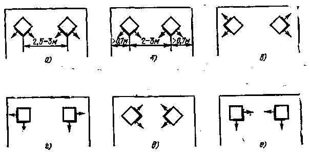
Fig.5
If the room is narrow, it is possible to send basic radiation loudspeakers in the side walls. Through reflection and re-emission from the walls it is possible to obtain the effect of the enhanced stereo (Fig.5,b,d). In the room of large dimensions, when the loudspeakers are placed relatively far from each other, you can create the effect of their approximation, which is necessary to direct the main radiation of the speakers towards each other (Fig.5,d,e).
By repeating design is recommended for each instance of a speaker on two head type GD-4 or HD-35 for low-frequency path and two heads for high frequency. The nominal power of the signal supplied to the loudspeaker, can reach up to 8 watts. When using heads type GD-36, which has a nameplate capacity equal to 8 W, allowed short-term overload up to 16 watts. Of course, the diameter of the cutouts in the panels should be coordinated with the dimensions of diffusionally domestic heads.
It should be noted that in recent years, a large number of Amateur and professional speakers, broadband and multi-band, in which the greater or lesser part of the radiation is directed towards the walls of the room. In the loudspeaker, which was discussed at a side of the radiation is given an average of about half the input power. The known design of the Amateur, where nine of the same broadband heads radiate in the front only ... one. The other eight are the main emission towards the rear, to the side walls, i.e. radiation in the direction the listener is consumed only 10% of the power supplied to the loudspeaker. However, the remaining 90% of the radiated power does not disappear without a trace. Radiation sideways and backwards, Bouncing off the walls and floor, partly reaches the listener in the form of scattered reflected signal, the perception of which creates the illusion of being in a spacious concert hall. Changing the position of these speakers relative to walls and floor, turning them in some way in the horizontal plane relative to the listener, you can achieve the best for the space of sound electro-acoustic equipment.
Three-way loudspeaker
About three-way speakers has already been said previously. In Fig.6 shows a sketch of the construction of the three-way loudspeaker. The body of the speaker is made of chipboard with thickness of about 20 mm at the Bottom of the hull is missing. Between the floor and side walls leaving a gap height of about 25 mm and a length of 200 mm. Its purpose is the creation of additional common-mode radiation at lower frequencies reproduced signal.
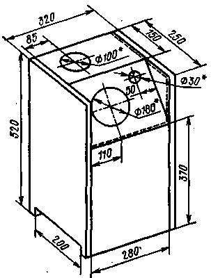
Fig.6
Unusual is the placement heads. So, midrange head is mounted on the upper wall. Low - and high-frequency head is placed on the inclined panel. Both panels, the top and angled draped fabric along the contour indicated in Fig.6, the dashed line, creating the illusion of a classic rectangular shape of the speaker enclosure. This placement of the heads allows the use of good reflecting and scattering properties of relatively low ceilings modern dwellings for the purpose of obtaining spatial rather than a point source of sound.
By repeating designs can apply a low-frequency head type GD-43, midrange head type GD-8TH and high-frequency head type DDG-31. This should be amended accordingly inclined upper and drawer panels. For the correction of high frequency resistance of the head parallel to its conclusions can be connected fixed resistors for 10-12 Ohms. In regard to the foregoing, the nominal power delivered to the loudspeaker, may be 5 watts.
Literature:
Publication: N. Bolshakov, rf.atnn.ru


