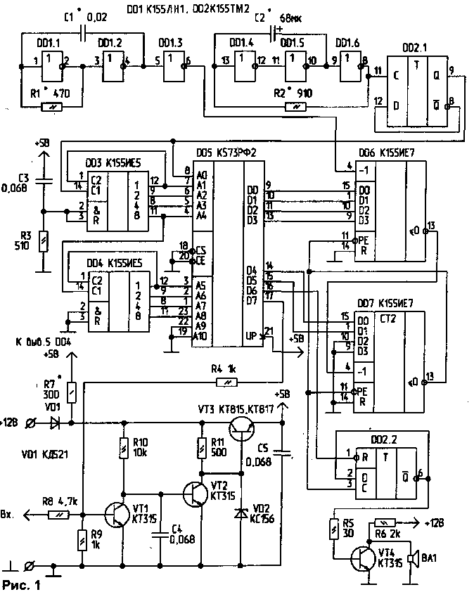
The proposed device, switch on signaling turns. When you turn left or right turn of sound fragments of melodies.
Based on the scheme of [1] describes in detail the work of the digital part of the device, given a table of programming the ROM. By the way, this table is wrongly printed extra lines OA0...11F. In the diagram (Fig.1) made some changes and additions. Specifies the tone generator is built on three elements DD1, generator cycles on the remaining three elements of this IC. Chain R3-C3 is used to set the counter DD3 to "0". Counter DD4 automatically busting tunes and for storing the number of the last fragment. To this end, the power is supplied to it directly from the vehicle electrical system through a ballast resistor R7. The input device connects to the warning light turns on the dashboard of the car.
A voltage regulator +5 V with an electronic key generates the voltage supply for the chip and stores it until the end of the tune. When you first switch (ignition) power is supplied to all IC, bit the end of a melody" (output D7 ROM DD5) has a logic level "1". This level opens the transistor VT1, which, in turn, closes the transistor VT2. On the Zener voltage VD2 is limited, and the stabilizer produces a voltage of +5 V. After the end of the melody output D7 appears logical "On", resulting in loss of power, and the monitor enters standby mode. When you turn on the turn to the base of transistor VT1 there is a voltage (warning lights), which includes a stabilizer. When this is set to "1" bits D7, and fragments of melodies sound until you turn off. After turning off the turn signal last melody completely. As the source of the sound system used BA1 type SN-2.

The design of the device may be arbitrary. In my case this fee size h mm, placed in the body HH mm Emitter is located inside the housing, but may be remote. The transistor VT3 is mounted on the heat sink (dimensions HH mm). Part of the joints of the printing installation, part - wire MGTF, some parts are soldered to the legs of the IC. The arrangement of parts shown in Fig.2.
The establishment of. The selection of resistor R7 to set the voltage of +5 V power supply pin IC DD4. The selection of elements R1, C1, R2, C2, set the required tone and tempo song playback. With proper installation and operational details of the detector works (tested on more than thirty instances).
Note. This alarm is designed for installation in cars "Lada", "field", "Volga". For installation on "Moskvich" signal from the lamp needs through the diode and resistor feeding the base of transistor VT2.
The dimensions of the detector may be further reduced, and the number of tones to reach 60...80 if all the address space of the IC DD5 codes to fill melodies, and instead of IC DD3, DD4 apply IC KIA. Power consumption can be reduced by using IC 555 series or 1533.
Literature
1. Evgrafov D. Musical machine. Radio, 1993, N7, Pp. 30-32.
Author: V. Gorkov, D. Bogodukhovka Omsk region; Publication: N. Bolshakov, rf.atnn.ru


