Among the variety of non-contact sensors, unpretentiousness to external conditions, ease of manufacture and durability of the most attractive induction (or generator) sensors.
Based on them were created by different instruments - from the simplest recording linear movement, to complex, such as ignition system with digital control, the fuel injection system, anti-lock braking system, brake control, etc.
Let us consider the process taking place in the generator sensor. In the simplest case, the sensor consists of a coil with a coil, a core of magnetic iron and magnet. These three components constitute the stator of the sensor. With the stator interacts rotor in the form of a gear drive or a rack with a number of teeth determined by the conditions of use of the sensor (Fig.1).
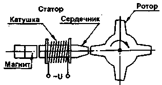
Fig.1
During rotation of the rotor in the stator winding and an alternating voltage. When one of the teeth of the rotor approaches the coil, the voltage rapidly increases and, when the coincidence with the middle line of the winding, reaches a maximum, and then, when you remove the tooth, quickly changes sign and increases in the opposite direction to the maximum. On the chart (Fig.2) clearly visible large steepness of the voltage change, so the transition between the two maxima can be used to control electronic systems.
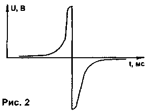
Fig.2
The voltage generated by the sensor depends on the rotor speed, the number of turns of the coil and the magnetic flux generated by a permanent magnet. Because the two quantities is constant, the magnitude of the induced voltage reaches a maximum at the maximum rotational speed. When you design should pay particular attention to the strengthening of pulses at low repetition rate.
The scope of such sensors is extensive let's look at some examples.
The sensor swing or stroke (Fig.3)
On the spiral spring made of wire reinforced a small piece of soft magnetic iron, when swing or push it interacts with the stator of the sensor, which produces a series of aperiodic pulses.
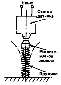
Fig.3
Rotometer (tachometer)
In the gauge of frequency of rotation of a crankshaft of the engine (Fig.4) the sensor stator fixed to the housing of the flywheel or on the stub observation hatch in the vicinity of the ring gear of the flywheel. The device provides the most accurate determination of the frequency of rotation without invasion in the circuit of the ignition system.
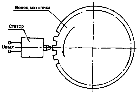
Fig.4
Speedometer
For measuring the vehicle speed toothed rotor is fixed on the output shaft of the gearbox or on the unit gearbox instead of the flexible shaft. The system eliminates expensive tachometer or mechanically unreliable flexible shaft (Fig.5).
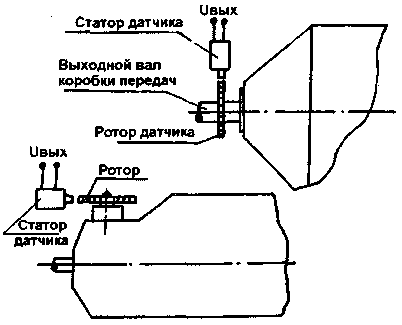
Fig.5
Odometer
Measuring the distance of a vehicle is performed using a toothed disk mounted on the non-drive wheel (Fig.6). Such sensors have also been used in the automatic braking system (ABS AntiBlockSistem), which prevents locking of the wheels of the vehicle and its drift from "Hughes".
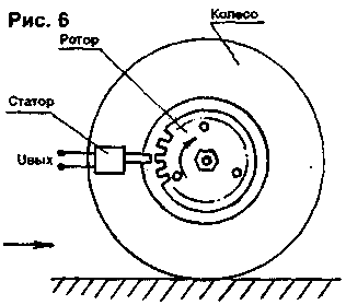
Fig.6
Wiper
Gear sector is fixed on the gearbox. Readings allow you to smoothly adjust the stroke frequency of brushes depending on weather conditions.
Ignition system
Generating the sensor (Fig.1) is the basis of the ignition system, Unfurnished.
In the ignition system with digital control "Impulse-Tech" Dr. Artiga used a flywheel ring gear of the engine with an additional tooth to produce a reference signal (Fig.7). This system allows very precise adjustment of the ignition timing.
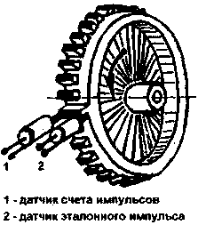
Fig.7
If you go back to the design of the induction sensor, it should be noted that if the speed of rotation of the rotor is affected by the parameters of the medium, then the question arises about the braking torque exerted by the magnetic field of the permanent magnet. In this case, measures are taken to increase the creep torque (increase the size of the impeller). If permit is not required to supervise a small rotational frequency, the core can be run from magnetic material without additional magnets, and due to the residual magnetism to obtain a sufficient value of the signal.
As an example, the parameters of the sensors, which found application in various devices.
For example, the sensor core is made of steel (CT1, CT2, CT3) 03...8 mm (Fig.1). At the core zapressovyvajutsja cheeks coil 012...20 mm 10...15 mm from each other. The core is under winding is insulated with PTFE film. Coil winding is performed in bulk, to fill the space between the cheeks. Wire - sew-1 00,06 0.1 mm....the Number of turns is approximately 2500...4000.
Core length ranges from 12 to 35 mm From one side of the core, there is a Playground for attaching an anisotropic magnet. Useful magnets from reed keyboards. The free end of the core is discharged from the housing. The sensor housing is made of nonmagnetic material. If conditions require the application of the sensor compound is poured.
The rotor, if it is necessary specially to produce, perform from of magnetic material. The number of teeth is determined from the operating conditions. The gap between the stator and the rotor should be as low as possible.
The signal from the sensor is input to a simple electronic circuit (Fig.8), amplifying and shaping signals for further use in analog or digital form.
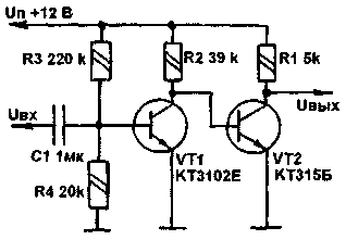
Fig.8
It is worth mentioning another feature of such sensors. They can read the signal not only from the special rotor, it may be the gear teeth or even mounting bolts on the rotating parts.
Literature
1. Boone B. electronics on the car. - M.: Transport, 1979.
2. Digital and analog ICS. The Handbook. - M.: Rice, 1989.
3. 750 practical electronic circuits. The collection, 1987.
Author: I. Semenov; Publication: N. Bolshakov, rf.atnn.ru


