


")

Burglar alarm for your car, you can buy ready-made. Manufacturing the same guard on your own, you will save not only money. Practice has shown that homemade device unlike the firm often complicates "work" the system. The author offers a simple, but quite reliable security devices, which can be assembled in three or four nights.
This switch delivers the alarm beeps when trying unauthorized entry into the vehicle or disassembly of its components. The device is powered by the on-Board network voltage of 11.5…14.4 V and consumes standby mode current less than 3 mA. Alarm - sound pulses with a frequency of review 1 Hz.
Schematic diagram of autostorage depicted in Fig. 1.
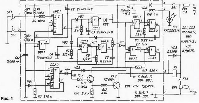
At power-up the switch SA1 through resistor R3 slowly begins to charge the capacitor C2. High level input voltage R triggers DD2.1 and DD2.2 (point a in the diagram) will install them in the zero state. The inverted output of flip-flop DD2.1 can quickly charge the capacitors C3 and C4.
The site, assembled on the elements of DD3.3 and DD3.4, generates a pulse of 400 MS, which will pass through the diode VD5 at the input of the current amplifier, harvested transistors VT1, VT2. This time period will trigger the relay K1, which serves load power transistor VT2. and Serena BF1 will submit a single short beep, indicating that power to autostorage filed.
After about 6 with capacitor C2 charges, the voltage at point a is reduced to the switching threshold of the CMOS elements and autostorage will be set to the standby mode. Inhibited generator configured on the elements of DD3.1 and DD3.2, will start to work with a frequency of about 1 Hz. HL1 led will flash to indicate that the entry autostorage in the protection mode.
Prior to the expiration of this time delay tt driver must get out of the car and close the doors, citing security contacts SF1 and SF2 in the position shown in the schema.
When opening car doors will close contacts SF2. At the output of the element DD1.1 appears a high level. This positive differential voltage will switch the trigger DD2.1 in one state, at its inverted output will be set low the level and begin to slowly discharge the capacitors C3 and C4. Once the voltage on the capacitor C4 reaches the threshold level, turns on the generator, assembled on the elements of DD1.3 and DD1.4. and will start to generate a pulse frequency about 2 Hz.
The pulses will arrive on the trigger DD2.2, included a frequency divider 2, and further through the diode VD4 to the input of the amplifier transistors VT1. VT2. As a result the relay K1 will be triggered and the 0.5 to let go of the anchor using the same pause the duration. Sound the siren, turn on contact To 1.1 relay K1 will begin play alarm sound pulses with a repetition rate of 1 Hz.
Chain VD7R11 contributes to a more precise turn the generator on the elements of DD1.3. DD1.4. After the first switching on the output element DD1.4 occurs the low level, the capacitor C4 is quickly discharged through the diode VD7 and resistor R11 and on the further operation of the generator is not affected.
While discharges the capacitor C4 (t2-5) the owner, upon entering the salon, time to turn the power off guard unit, otherwise the unit will work and will include the alarm signal.
In the case when the watchdog is triggered, the alarm will sound until then. for discharge of the capacitor C3. Once this happens, the element DDI.2 switches in one state and are similar to the above will install the device again to the standby mode under the condition that the contacts SF2 to this point will be open. If they remain closed, the alarm will be cyclically repeated. The duration t3 of this cycle is about 35 C.
All three temporary excerpts t1 - t3 can be adjusted by the relevant choice capacitors C2, C4 and C3.
Diode VD8 protects the detector from the erroneous inclusion of the supply voltage in reverse polarity. The capacitor C6 smooths out the ripple of the supply voltage, regarding the work of the watchman.
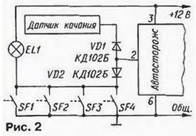
Security sensors SF2 - contacts, installed on the doors of the vehicle interior (conventionally, the diagram shows one pair of contacts; really valid to include in parallel to ten pairs, including sensor swing). If the sensors used existing door switches for interior lighting, we need to "unleash" the separation diodes VD1 and VD2 (Fig. 2).
A group of sensors SF1 (which also may be a few, but included series) mounted on the Windows of the cabin. Structurally, the sensors glasses" can be different - ready switches to a homemade foil or wire (with a diameter of 0.05 mm or less) of the labels on the glass surface.
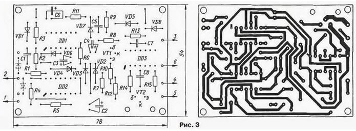
Most of the parts of the device mounted on a printed circuit Board of foil fiberglass thickness of 1.5 mm. Drawing Board depicted in Fig. 3. On the Board provides space for the mounting of the barrier diode (VD1, VD2 in Fig. 2). Fee reinforced durable duralumin or steel box.
Transistors CTA and CTA can be replaced by CTA and CTA respectively. Power transistor VT2 must be installed on a heat sink with cooling area not less than 6 cm .
Oxide capacitors - C50-35; the rest K73-17. Diodes VD1-VD7 - any of series KD521 and KD522. Relay K1 - RES, passport RF4.500.129 or automotive relay RS.
As sirens BF1 suitable available on the car alarm sound (the horn), but it is better to use a siren from one of the imported devices alarm. Sirens come in different capacities - 5.10 and 20 watts. At high power signal to the guarded machine sounds very loud, but the battery, naturally, more quickly. One can not ignore the fact that excessively loud noises disturb the neighbourhood. Therefore, the choice of optimal power siren it should be given due attention. Recommended types siren - BS37-PO, SAETAN-SN.
The correct approach to the selection of power sirens in some specific cases, allows to increase the reliability of protection of the vehicle using an alternative source power guard - standalone compact battery rechargeable from the electrical system while driving.
Many consider it desirable to Supplement watchdog light the alarm system. It is easy to implement, using free relay contacts or by connecting the lamps in parallel to Serena, it is only necessary to consider load the ability of the contacts. As an extreme measure can be recommended installation instead one of the two relays in parallel. In this case, the resistance of the resistor R8 is necessary reduce three times.
Author: O. Czerski, Lviv, Ukraine
Refinement of this device