Many families have historic or just old clock - wall, outdoor, fireplace, "clocks" - quite a decent sort, but with the mechanism, long time a worn and beyond repair. To "revive" such a watch, author offers to install them in a stepper motor (SM) and a small electronic unit. Watch not just "go", their progress will be stable quartz resonator.
In a mechanical watch, most often fails escapement, synchronizing movements with oscillations of the pendulum or balance wheel. To repair it under force only to an experienced clockmaker. The cost of such a repair quite expensive, especially if the watch is long out of production and spare parts to them is not. However, part of the mechanism that directly links with arrows, as the rule remains intact. By setting in such a watch stepping motor (SM), you can turn them into Electromechanical, capable of regularly serve another many years.
Fairly detailed information about the device and principle of operation of the SM can be found in article L. I. Ridica "stepper motor Controller", located on the Internet. They are widely used in computer disk drives, printers, scanners, copiers phones and many other devices. To drive hours to fit almost any. Even motors with rated operating voltage 24...28 V develop sufficient for such application of torque when powered by a voltage of 5 V.
The most common stepper motor, the rotor of which rotates in 15° increments (step 24 the turnover). Among them FB-20-4-1, DS-0.25 A, СLW 15/100. Rarely come across engines step 11° 15' (32 steps per revolution), for example, DSM-50/8-0.47. The rotor is very convenient and compact motor DSHI-200-1-1 makes a complete revolution for 200 steps.
If the functions are available SHD unknown, should be measured with an ohmmeter the resistance between them (each to each). Given that all windings have approximately the same resistance, based on the measurement results it is easy to determine the number and the wiring diagram. Scheme some common SM it is shown in Fig. 1, a-C.

Alternately feeding on winding voltage SHD and watching in which direction and the angle that rotates the rotor, determine the switching sequence windings (Phase 1 - Phase 4), providing uniform rotation of the rotor in one side. When switching of the windings in the reverse order (Phase 4-Phase 1) rotor must rotate in the opposite direction. It remains to count the number of steps the rotor of the stepper motor makes a complete revolution.

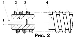
Shaft SM is the easiest to associate with the axis of the second hand of the watch. However, the arrow's will have to remove from the face, because after alterations it will move irregular 2...2.5 s. the Connection is performed, as shown in Fig, 2. Axle seconds 1 skewer cylinder 2 made of plastic (organic glass, the PCB, ebonite, etc.), external diameter equal to the diameter of the shaft 4 SM. The cylinder 2 and the shaft 4 connects firmly attached by a suitable spring 3 internal diameter. In this connection it is not necessary to strictly observe the alignment.
If the second hand in the clock is missing or not designed for to attach to an axis of the SD, it is possible to transmit the rotation to the axis of any of numerous gear wheels of a watch. It is only necessary, by counting number of teeth in pairs, to determine the gear ratio between the shaft SM and the axis second or minute hands and matching the frequency applied to SHD pulses.
In order not to create unnecessary load on the engine, one or more gear sets between the axis and which is connected with its shaft, and an anchoring mechanism better hours delete. You must remove and available in hours drive - spring or weight lifting.
In the clock mechanism usually includes a clutch that allows you to move arrows manually, which is easily to find on the typical three-beam steel spring. It must be locked. Not otherwise excluded slippage clutch under the action of creating SHD pulse mechanical loads, the resulting clock will be noticeable lag. Easiest way to do it, solder the spring to the gear on which it slides when you move the arrow.
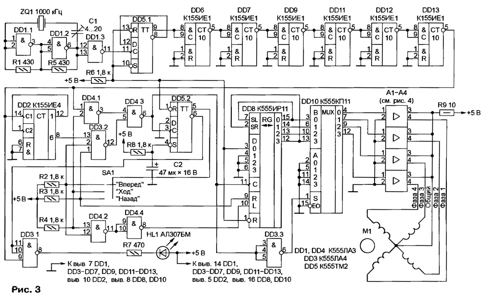
The generator control pulses, the circuit of which is shown in Fig. 3, is designed for stepper motor with 24 rotor per revolution, the rotating axis of the second hand of the watch. The desired speed (1 min-1) is received, if the pulses at the output the master oscillator on the elements DD1.1 and DD1.2 have a frequency OO kHz. Achieving accuracy, adjust the frequency within a narrow range of the trimpot the capacitor C1.

For SM with a different step value will proportionally change the resonant the frequency of the crystal. For example, when 32 steps per revolution is required quartz frequency 1000-32/24=1333,3 kHz. The desired result can be achieved changing the schema of a frequency divider. In this case it consists of a trigger DD5.1, counters DD6, DD7, DD9, DD11 - DD13 and DD2 General conversion factor 24000000. The frequency of the master oscillator or the ratio of the divider you will need to change if the rotor SHD not connected with the axis of the second arrow.

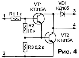
The required switching sequence of the windings SM M1 provides shear register DD8, the outputs of which are connected with the windings through the multiplexer and DD10 the same transistor switches A1-A4, collected according to the scheme shown in Fig. 4. The multiplexer DD10 shortens the pulses of current in the windings SHD twice. The amplitude pulses is limited by the resistor R9 of the General circuit of the windings. These measures increase the efficiency of the device. If the element D3.3 to replace the single-shot launching the front of the pulse from the output element DD4.3 and forming a short permitting momentum, the average current consumed by the motor can be reduced even more.
At the time of power-up logic voltage levels at the inputs 9 and 10 register DD8 high. This corresponds to the parallel recording in the register code submitted on its inputs 3-6. Therefore, with the receipt of the input register 11 the first pulse at its output 15 will be set high, and the outputs 12-14 - low level. Chain Phase will be connected to the common wire, and through the corresponding winding of the stepper motor M1 current flows. The engine will make the first move. The same the pulse sets the trigger DD5.2 low level at the output 5 and high output 6. HL1 led is flashing with a frequency of 0.5 Hz.
A low level at the input 10 DD8 will put the register in the shear mode in code from Junior to senior level. If the switch SA1 is set in position, a low level on input 2 element DD4.1 will prohibit the passage of through pulses of a higher frequency from the output of the counter DD13. Pulses the nominal frequency 24/60 Hz from the output 8 of the counter DD2 is input to the register through the elements DD3.2 and DD4.3.
When the switch SA1 in the "Forward" or "Back" passage the nominal pulse frequency input to the register DD8 will be banned, and high - permitted, leading to accelerated motion arrows in the corresponding direction.
Author: A. Maravich, Voronezh


