


")

Time relay, we offer our readers, is used in devices automation in the workplace and in everyday life. The device is simple in construction, has small size, reliable in operation, but its main feature is a large the range of exposure.
Construction electronic time relay on the principle of charge-discharge capacitor to extract more than 10 minutes is a difficult task. High resistance discharge circuit exposed to climatic factors (especially humidity), and, if not to take special measures, its stability is low.
Time relay, which uses a reference oscillator with frequency dividers and decoder, are less susceptible to external influences. Therefore, these devices with much (higher stability may build endurance in the tens and hundreds of hours. However, to make the such devices difficult.
Design mentioned in this article combines the advantages of these devices and at the same time available to repeat in Amateur conditions. Schematic diagram time relay presented on figure 1. Transistors V1 and V2 with elements of D1.1 and D1.2, the capacitors C1 and C2, resistors R3, R4 and R5 form a generator; the frequency of its installed a variable resistor R4. The generator output is connected to the frequency divider, assembled integrated circuits, D2 - D6. With his exit from the come to one of inputs of an RS flip flop, assembled on the elements of D1.3 and D1.4. The other input of the trigger is connected to the trigger circuit.
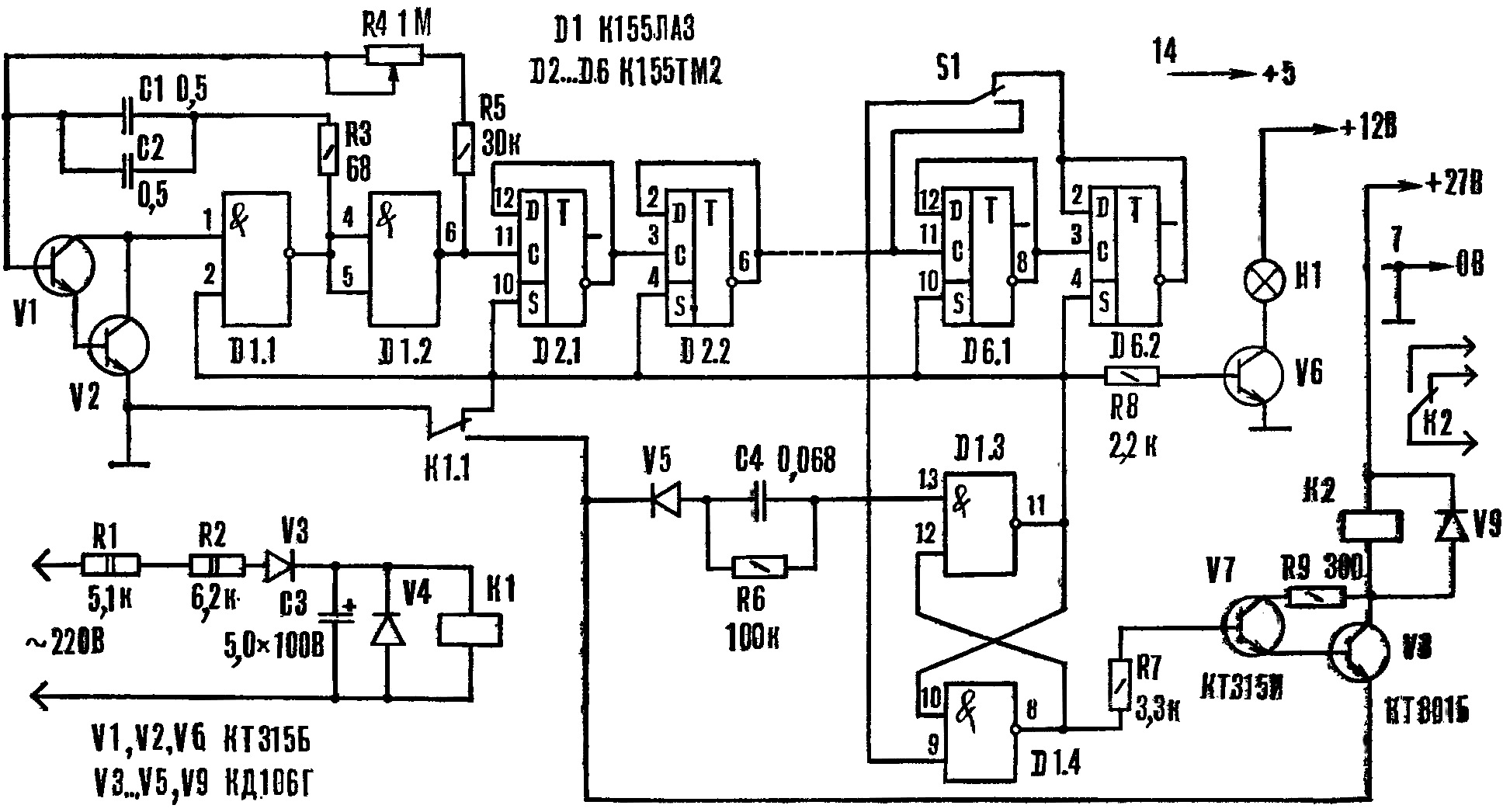
Fig. 1. A schematic diagram of a timer (click to enlarge): K1 - RES-10 (passport RS4.525.301), K2 - RMU (passport RS4.523.303), H1 - CMH-10-55
One output RS-flip-flop is connected via the transistor to V6 indicator light H1 and the second through the transistors V7 and V8 to the relay K2.
Running an AC voltage of 220 V is supplied through the quenching resistors R1 and R2, diodes V3 and V4 and the capacitor C3 to the relay K1. In the original state when the triggering voltage is not present, the contact K1.1 closes generator, and it does not work. Triggers frequency divider are also a starting position: signal lamp H1 is not lit. Relay K2 is de-energized, though to the base of transistor V7 enjoyed a high level voltage (emitter V8 disabled from the "common" wire).
When there is input signal, the relay K1 is actuated and its contacts K1.1 switch. At this point, the RS-flip-flop changes its state on opposite - at pin 11 of the element D1.3 becomes a high level voltage, and the output 8 of D1.4 - low. Signal lamp H1 lights up however, relay K2 remains energized, as based V7 appeared low the voltage level. The generator produces pulses that come to the frequency divider. With the advent of the low level at the output of the last element frequency divider RS-flip-flop switches to the original condition at the conclusion 11 element D1.3 becomes low level, and the output 8 of D1.4 - high. The generator is interrupted, the lamp H1 goes out and the relay K2 is activated (the contacts K1.1 remain closed until the disappearance of the triggering voltage).
The device performs the delayed arrival of Executive stress relative to the trigger during the set shutter speed. It is set the frequency of the oscillator through resistor R4, and a large-scale switch S1. It is clear that the higher it is, the shorter the exposure time, and the more the division ratio of the frequency divider, the longer. The frequency of the oscillator you can rebuild smoothly within wide limits, and the division ratio is jump 4 times. The scale of the relay corresponds to 6 min, and the closure of S1 becomes equal to 1.5 min.
To build a timer with the shutter speed at 24 min, enough to add another single chip K155TM2. Thus, the addition of one chip increases the exposure time by 4 times. While increasing the capacitance C1, C2 or the resistance of the resistor R4 should not be, because deteriorating the stability of the first pulse generator.
Correctly assembled device begins to work immediately. Adjustment is reduced to the graduations of a scale that is almost uniform in the application of linear resistor (R4). The calibration is easy to perform, if after the first element frequency divider to measure the pulse width and multiply by a factor dividing the remainder of the divider.
When measuring the output 9 of the element D1.4 disconnect and start the generator. Like this the calibration method significantly reduces the time to conduct this operation, because they do not need to wait until the end of the period of maximum exposure.
After graduation, circuit relays restore. To the output 11 of the element D1.3 connect electronic stopwatch and additionally test the correctness of the of the grading scale.
Time relay, collected on chips series K155, sensitive to noise, penetrating power circuits. So they need to block capacitors.
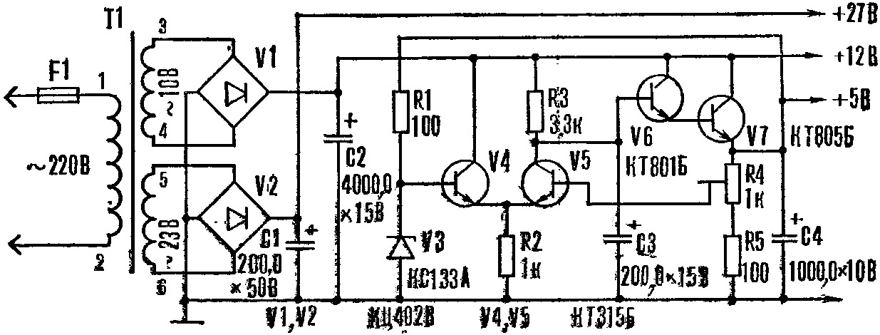
Fig. 2. Schematic diagram of power supply (click to enlarge)
The power supply, the circuit shown in figure 2, is designed to the kit consists of six relays.
T1 is made on the core from a TV transformer TCE-110. The primary winding (pins 1-2) wound wire sew-2 0.12 and contains 1760 turns, the secondary winding (pins 3-4) has 90 turns of wire sew-2 0,71, third (findings 5-6) - 200 turns of wire sew-2 0,21.
Author: Oleg Lazarenko