


")

The practice of using cheap imported electronic devices internal clock revealed significant instability of the current readings time. About the reasons of this phenomenon and the ways of overcoming this drawback described in this article.
Most unreleased until recently, foreign radios (even well-known companies) with integrated digital electronic clock big sin the lack of precision. This, in particular, relates to a clock radios Sony model "ICF-C760L", Panasonic model RC - E" etc. the fact is that asking for time circuits is the frequency of the electrical network. So on weekdays, when a heavy load, and accordingly the frequency is below 50 Hz, clock, usually behind, and on weekends, at low load, - were exactly or even hurried. And only recently, manufacturers began to apply in such devices quartz stabilization of the nominal frequency.
To work hours in the previously released models of radios, the clock radios and other products powered by the network to make accurate, it is necessary clock frequency shaping generator with quartz stabilization. But the relative complexity of this task is that the frequency standard watch crystal 32 768 Hz is not a multiple of 50, and the use resonators at higher frequencies requires a large number of chips for build the required frequency divider [1] or specialized chips dividers. For example, if the oscillator frequency of 1 MHz it is necessary to construct the divider 20,000.
Completion of hours in which the frequency of 50 Hz is used for dynamic display mode described in [2]. If the clock applied a static display, task can be solved much easier.
The processing unit clock signal (its schema is shown in the figure) allows you to solve the problem by using a standard watch crystal resonator and two chips. However, it utilizes not the usual way the formation of the desired frequency. For the chip clock is not so important - whether on the clock input pulses with a frequency of 50 Hz evenly over time or use a short sequence of 50 pulses greater frequency in within 1 s. In the proposed device are formed in a second two packs of 25 pulses each.
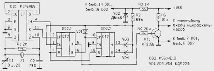
Formation of the required time intervals, and sequences pulse performs DD1 chip. Chip KIA functionally consists of generator part connected to the quartz resonator, and two counters-dividers with a total multiplier 215 . The output of the discharge 14 frequency divider circuits DD1 (pin 4) is connected to the reset inputs R of the binary counters DD2.1, DD2.2. Rectangular pulses arriving at the inputs R of these the meters have a frequency of 2 Hz.
During the first half of the period equal to 0.25, log. 0 enables the counters DD2.1 and DD2.2. In the second half of the period log. 1 resets the counters and keeps them in this state until the beginning of the next period. Rectangular pulses with a frequency of 32768 Hz output To DD1 chip (pin 11) is transmitted to the counting input CP of the counter DD2.1. Four-digit binary counters DD2.1 and DD2.2 are connected in series. The first three digits DD2.1 divide the input frequency by 8, and the fourth discharge DD2.1 and all bits DD2.2 together with the diodes VD1, VD2, and VD3 resistor R2 form a counter 25 with the lock.
Thus, received a five-digit counter counts the pulses, received from the output of the frequency divider 8 (the output is W-rd and 4-th level DD2.1). While at least one of the terminals 6, 13 or 14 of the chip DD2 the level of the log. 0, log CN (pin 1 DD2.1) also saved a log. 0, which permits the passage pulse input CP (pin 2 DD2.1). After the pins 6, 13, 14 set individual levels that correspond to the decimal number 25, at the entrance CN will log. 1 and block further passage of pulses. So by the way, for those 0.25 when there is no signal to the reset inputs R, the output 4 of counter DD2.1 25 is formed of pulses with a frequency of 4096 Hz (32 768:8). These pulses through the switch transistor VT1 is served to the clock input of the chip hours. In the next 0.25 counters will be in the source condition, during the second period of the whole cycle will repeat.
The device, made according to the proposed scheme, installed in the radio Philips model "AS 470" and works with chip hours MM. Device powered by the same source, and clock radio. The output signal is fed to the clock input of the chip clock is coming to that point of impulses 50 Hz with winding of the power transformer and half-wave rectifier. If you install to a different radio, where the power supply voltage the clock chip is 9…12 In the diagram you can eliminate the resistor R3 and Zener diode VD2.
Literature
Author: D. Berdichevsky, Moscow