The materials on the control of rodents using a variety of electronic devices already published in the magazine "Radio". In the present article describes another device of similar purpose, which differs from the already known ability to work in conditions of significant temperature fluctuations and moisture, economical, simple circuit decision. It does not require complex instrumentation.
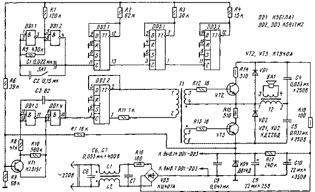
A schematic diagram of an electronic device for repelling rodents is shown in Fig. 1. It consists of a bass generator, frequency divider, ultrasonic frequency generator, the signal generator of the "meander", a power amplifier and audible alarm.
The bass generator assembled on the elements DD1.1, DD1.2 DD1 chip. The repetition rate of the generated rectangular pulses is determined by the values of resistor R5 and capacitor C1. On closure of switch SA1 in parallel with the capacitor C1 connects an additional capacitor C2, which reduces the frequency. To make it harder for rodents adaptation to chilling signal, the switch SA1 is necessary to change one or two times a week.
From the output of the low frequency signal generator is fed to a three-digit binary counter-divider is made on the elements DD2.1, DD3.1 and DD3.2 and counting to 16 in the code 1-2-4-8 (Junior category is pin 3 of the element DD1.1). The outputs of the counter are connected to the resistors R1-R4, converting the binary digital code numbers from 0 to 15 V analog signal, i.e. the voltage changes from zero to a logical unit (12B).

Each MSB of the counter is turned on through the resistor is twice lower ranking than the younger. With this combination, the inclusion of resistors R1-R4, the voltage at their point of connection is equal to zero when all bits of a logical zero is present. At each switching of the multivibrator DD1.1, DD1.2 this voltage abruptly increases by 1/16 of the supply voltage (u pit). 16 switching cycles counter reaches the status of 1111, and the voltage at the junction point of the resistor is maximum, i.e. u pit. The next time you switch counter is reset to 0000 and the cycle repeats.
Resistors R1-R4 can be installed on the connectors that gives you the opportunity to rearrange them, in this case, each of the 16 States of the counter will correspond to one of 16 voltage levels. Each combination of these resistors corresponds to a certain sequence of changes in the control voltage. The number of such combinations is N is equal to the factorial of the number four:
N=4!=1X2x3x4=24.
Such a variety of laws modulation of ultrasound can also be used to prevent adaptation rodent deterrent to the signal of the electronic device.
On the elements DD1.3, DD1.4 is assembled, the generator of ultrasonic frequency, which is determined by the capacitance of the capacitor NW and mode of operation of the open transistor VT1. The mode depends on the control voltage supplied through a resistor R6 to the base of transistor VT1. When specified on the circuit component values and the change in the control voltage from 0 to 12 V, the oscillator frequency varies from about 50 to 100 kHz.
From the output of the ultrasonic generator is modulated by the frequency of vibrations received on the D-flip-flop DD2.2, which divides the frequency by 2 and generates the output signal of the "meander" required for a symmetrical output stage. Loaded D-flip-flop to the primary winding of the transformer T1 is connected to its output through a resistor R11. This reduces the current load of the trigger and contribute to a better functioning of the output stage.
More detail should dwell on the circuitry of the output stage of the power amplifier, and method of supplying power to different parts of the device. Given the conditions in which to work such devices, the traditional scheme of power supply (transformer-rectifier-stabilizer) to use impractical. The fact that small-sized network transformers in areas with high humidity are unreliable: the magnetic core is exposed
corrosion; in the primary winding is often damaged insulation and there are breaks because it applies a very thin wire. As for linear stabilizers, they have a significant disadvantage - from 20 to 50% of the power dissipated in the regulator, which does not meet the requirement of efficiency. That is why for such devices it is recommended to use transformerless.
The emitter in this rodent repellent is usually four, shestibalny tweeter. As the audit showed, after a few days of work most heated part is precisely this head. For greater reliability of its capacity should be about 3...3.5 watts. At a voltage of 300 V, the current consumed by the power amplifier, will be 10... 12 mA. Low-voltage part of the device assembled on the IC consumes about b...7 mA. Such values of currents allowed low and high voltage parts to be connected in series and feed them from a common power source voltage 300...310, consisting of a bridge rectifier and VD3 filter capacitor C10. The power IC stabilizes the Zener diode VD4. Thus, there is no need to develop additional supply voltage of the IC, for example, using the quenching capacitor and the diode bridge.
The power amplifier is a half-bridge inverter, collected on transistors VT2, VT3, and the capacitors C4 and C5 (MoES V. S. Stabilized transistor converters. - M.: Energoatomizdat, 1996). It utilizes the cheapest of the number of high voltage transistors CTA. The voltage at the collector close to the maximum, but as the test showed, this node is able to operate even when the voltage V. 335
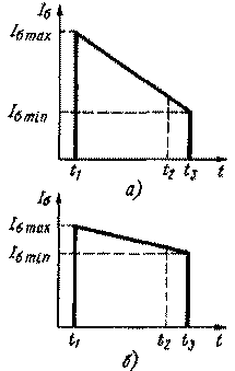
The use of high-frequency transistors partially solves the problem through current. For protection from him and taken other measures. So, the inclusion of resistors R14, R15 in the circuit the collectors of transistors VT2, VT3 limits their currents even if a short circuit in the transformer T2 or load. Dissipated in the resistor power is 0.1...0.15 W, which reduces the efficiency of no more than 5 %. Super-saturation of an open transistor is eliminated by limiting the base current via the resistor R11. And it is better than to be used for current limiting base resistors R12, R13, because in the first case, the base current during the time the presence of an opening pulse is of a decreasing nature. In Fig. 2 shows the form of the base current by limiting it to a resistor R11 (Fig. 2A), and resistors R12, R13 (Fig. 2,6).
When the transistor is in key mode, it is necessary that it is in a saturated state CNAS=IB/(I a/h21e)>1 for almost the whole duration of the opening pulse. As shown in Fig. 2,6, this time corresponds to the period t1-t2. Only at the end of the pulse (t3-t4) need to reduce the base current to the coefficient of saturation of CNAS approached 1. This will reduce the switching losses in the transistors. However, it should be recognized that this method of reducing the switching loss is effective only for fine-tuning the output stage, and this is possible at a constant pulse duration (t3-t1=const). Since in the described device the mentioned condition is not met, it is impossible and fine tuning of the cascade.
Through the resistor R17 is leaking a small amount of current for start-up the device when you enable it in the network. Filter L1 L2C6C7 protects your network from interference from rodent repeller. In the author's version of a device placed on a printed circuit Board IC, the transistor VT1, and the associated resistors and capacitors, and a Zener diode VD4 and capacitors C8, C9. For the remaining parts used point wiring on a piece of fiberglass. Transistors VT2, VT3 attached to the Board using the M3 screws and nuts.
The device may be applied to the resistors MLT specified in the scheme of power. The capacitors C4 and C5-C7 - K73-17, C9, C10 - C50-29 or K50-35, the rest is all-ceramic. For winding chokes L1, L2 and transformer T1 suitable ring cores Khj,5, KHZ, CHB etc ferrite. Coils L1, L2 contain 20 turns of wire folded double PELSHO of 0.25. 1-2 winding of the transformer T1 contains 210 turns of wire PELSHO 0,1, windings 3-4 and 5-6 - 18 turns PELSHO of 0.25. The transformer T2 can be wound on a ferrite ring cores CHB, Chg, CHH and even W-shaped ferrite magnetic core, for example, from the blocking transformer old tube TV. 1-2 winding comprises 200 turns of wire PELSHO 0,2, 3-4 - 8 turns of wire PELSHO of 0.3. All magnetic cores made of ferrite brands NM, 2000NM NM. Chip CLA and CTM can be replaced by the corresponding series 564. Instead of transistors CTA permissible to use CT, CT, CT and others high voltage. The switch SA1 - P2K or any other small, dynamic head - 4ГLW-1.

For adjustment of the device requires an external power source voltage 20...25 V. First separately adjust the part that is mounted on the circuit Board. Power source (polarity!) through the resistor 0.62...1 kω is connected to the capacitor C9. The operation of the generator is low and the frequency dividers can be checked using the led. The cathode of the led being served to the negative terminal of the capacitor C9 and the anode through a resistor of 5.1... 10 kOhm - alternately to the bottom (the scheme), the findings of the resistors R1-R4. The flashing frequency of the led each time should decrease twice. On closure of switch SA1 frequency falls several times.
In the presence of an oscilloscope or frequency counter to check the frequency range generated by the ultrasonic generator. To do this, reduce the frequency of the generator LF, instead of connecting the capacitor C1 to the capacitance of 2.2 to 4.7... UF and instead of the R5 resistor 1...3 Mω. The frequency alternately measured on pins 1 and 2 of the chip DD2. It should take 16 different values, from about 25 to 50 kHz. If necessary, the frequency range can be adjusted by resistors R6-R10: divider R7R9 sets the center frequency; if you decrease the resistance of the resistor R6 increases the deviation; resistors R8, R10 ensure the uniformity of the frequency change. In the absence of measuring devices to confirm operability of the ultrasonic generator can by placing it in the audio range. For this purpose parallel to the capacitor NW connect an optional capacitor 820 3300... pF and using a high-resistance telephone connected to the terminals 1 and 2 of the chip DD2, listen to it, the frequency with which switches the trigger. After that, by setting the resistor R5 and capacitors C1, NW indicated in the diagram of the values, proceed to configuring the device as a whole. The elements of the device have a galvanic connection to the mains supply, so setting it up is necessary to observe precautions!
The circuit Board is connected to the transformer T1 according to the schematic diagram. IC is fed from an external source. At the output stage serves full meals, connecting the negative terminal of the capacitor C10 to the emitter of the transistor VT2. If errors in the Assembly and no parts serviceable, the output stage will be available right away. You only need to install the required output power. To do this, measure the voltage drop across the resistor R18, it should be 1...1.2 V. At lower voltage winding 3-4 of transformer T2 should be increased by 1-2 turns, with a larger decrease for the same number of turns. If the transistors VT2, VT3 are heated, it is necessary to reduce the resistance of the resistor R11. After carrying out these operations is disconnected from the IC external power source and all connections are made in accordance with the circuit diagram.
Author: I. tanasiychuk, Storozhynets, Chernivtsi oblast; Publication: N. Bolshakov, rf.atnn.ru


