The profitability of beekeeping farms depends on the health of bee colonies in the period of collection of honey. Great economic damage to large apiaries, numbering several hundred hives, causing, for example, uncontrolled swarming. Developed many technological methods of its prevention, but they are all very time-consuming, require disassembly of hives and intervention in the life of bee colonies. To successfully apply these techniques, it is very important to promptly and accurately identify biological condition of the bees. It will help to make the proposed device.
Attempts to construct a device for acoustic diagnostics of biological conditions bee colonies have been repeatedly [1]. The principle of operation of most known devices is that generated from the acoustic colony noise filter emit a narrow bandwidth centered on a frequency of 240 Hz. It is assumed that the presence in the spectrum of the noise components with frequencies close to specified, indicates a low activity of bees. But such tests devices in the real world does not give positive results. The main reason their poor performance is the wrong choice of criterion evaluation state bee colonies.
The fact that components with frequencies close to 240 Hz, are present in created by bees noise always. Their intensity depends not only on the biological status of the family (e.g., swarming), but also on other factors, for example, the number of bees in the hive. So the readings that measure absolute the value of the noise intensity, unreliable, and unsuitable for devices beekeeping practices.
To the readings depended on the biological status of bee colonies, you should evaluate the ratio of the intensities of the two narrow-band noise signals, allocated in different frequency areas. In [2] it is shown that the active the state of bee colonies (spring development, honey yield) characterized by a maximum the intensity of the spectral components in the frequency band 260...320 Hz. When the decrease in the activity (swarming, disease, absence of the uterus) maximum range shifting to the area of 210...250 Hz. Determining which of the specified ranges the noise intensity is more, it is possible to judge about the state of bees.
The proposed acoustic diagnostic device operating according to this principle, equipped with two led indicators: "Yes" and "No" . There are three the operation mode. The first one is "P" (passive state) - designed for detect idle state of bee colonies associated with, for example, swarming, no place to brood or overload sockets honey. Weak compared with the indicator "Yes" glow indicator "No" means that accumulate in the hive inactive bees and the colony in the coming days will be included in the swarm stage. In the "M" mode (reception of the uterus) identify the family to implantable Queen, which can be accepted ("Yes") or rejected ("No"). The status of wintering bees appreciate in mode "3" (wintering). It is satisfactory if burns the indicator "Yes" or bad otherwise.
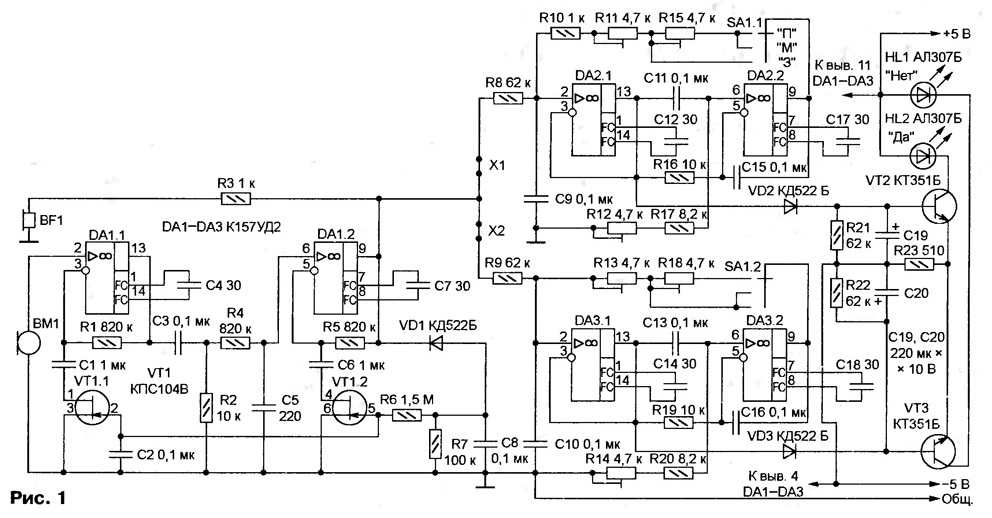
Diagram of the device shown in Fig. 1. Two-stage amplifier with automatic gain control, built on a chip of DA1 (CUD), is designed to enhance the audio signals received by microphone WM. Between the two cascades of the power amplifier a passive bandpass filter C3R2R4C5 skipping frequency from 160 to 890 Hz.

(click to enlarge)
The signal from the output of op-amp DA1.2 arrives at the inputs of bandpass filters, and through the resistor R3 - a Cup BF1 for auditory monitoring. This same signal is supplied the AGC detector (VD1). The change in the noise level leads to a change in bias the gates of field-effect transistors VT1.1, VT1.2, the resistance of channels and depth feedback, which covers the stages of the amplifier. As a result, when the oscillation the intensity of noise generated by the colony, the voltage signal at the output the amplifier is maintained.
Two of the bandpass filter is isolated from the noise spectrum narrow areas, the ratio the signal levels of which carries information about the state of bees. Both filters built on the same circuits on chips DA2 and DA3. Oh each of them connected so that they form gyratory. Equivalent inductance gyration are with capacitors C9 and C10 parallel oscillatory contours. From the values of resistors R8 and R9 depends the quality of the contours and width the bandwidth of each filter. Rigged by the resistors R11, R13, R15 and R18 (depending on the position of the switch SA1) filters set up on the frequencies listed in the table.

Using resistors R12 and R14 are making the maximum figure of merit contours: when removing the jumpers X1 and x2 filters must located on the border of self-excitation.
The filtered signal through half-wave rectifiers diodes VD2 and VD3 arrive at the inputs of the differential amplifier transistors VT2 and VT3, employee node comparison. In the collector circuit of transistors included LEDs HL1 ("No") and HL2 (Yes), the comparative brightness of which is indicative on the state of bee colonies.
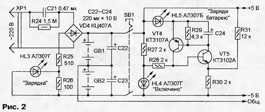
Node circuit supply device shown in Fig. 2, and the numbering of elements continues in Fig. 1. Here are two of the battery GB1 and GB2. Each consists of four accumulators D-0,26. The device includes a push-button switch SB1. Power consumption is less than 25 mA, and a fully charged battery lasts for 2000 sessions of the measurement duration by 5 seconds.

The trigger transistors VT4, VT5 different patterns is used to control the voltage batteries. Exemplary is the voltage drop across the led HL4, signaling device is turned on. When the total voltage of batteries GB1 and GB2 above 7 In the voltage drop across the resistor R30 exceeds exemplary, transistors VT4 and VT5 are closed, the HL5 led is not lit. When the battery voltage is below the specified trigger changes state, the transistor is opened, the led HL5 signals the need to charge the batteries.
Node battery charging from the mains is made on a simple scheme with damping the capacitor C21. It also includes VD4 diode bridge and resistors R24 - R31. During charging, the HL3 led glows. Complete recovery capacity battery is 14 hours
The design of the device can be any. It is important to ensure the convenience of its use and carry. In the original it has the dimensions 260x180x70 mm and weighs 1.4 kg.
To configure diagnostic device, you need a generator 3H and millivoltmeter AC. Millivoltmeter connected to the output of the first bandpass filter (the pin 13 of the chip DA2) and GND. Removing the jumper X1, trimmer resistor R12 introduce a filter in the generation mode, fixing the origin of oscillations the deflection of the needle of the millivoltmeter. A small rotation axis of the resistor R12 in the opposite direction tear generation.
Connect the output of the generator 3H left-hand schema of the output resistor R8 and, in switch SA1 and trimmer resistors R11 and R15, set up the filter on listed in the table of frequencies. To start setting resistor R11, setting the switch SA1 in position "3". In the provisions of "M" and "P" found the position of the axis of the resistor does not change.
Connecting the voltmeter to the pin 13 of the chip DA3 and removing the jumper x2, similarly, using the trimmer R14 achieve the generation and her breakdown in the second filter. Then adjust the filter to the desired frequency trimmer resistors R13 (SA1 - in position "3" or "M") and R18 (in position "P").
Once configured, jumpers X1 and x2 set in place. The operation of the device in generally you can check by submitting the signal generator 3H on a small dynamic head and placing it near the microphone WM. Adjustment frequency generator maximum brightness LEDs HL1 and HL2 needs to match the frequency settings of the filters and hardly depend on the sound volume.
To check the status of bee colonies microphone of the device is placed on the canvas, covering frames with bees. Put insulating cushion to dampen external noise. The device is then turned on for a few seconds, watching the LEDs HL1 and HL2. Diagnosis in ' M ' mode is carried out after the hive in "the cage Titova" placed the Queen. After about half an hour, you can determine whether it bees.
Literature
Author: I. Bakouchev, Ulyanovsk


