


")

Using fresh water for cooking or drinking, it is desirable to clean it from any impurities. Mechanical impurities are suspended solids (sand, clay, rust, etc.). On the surface of the water basins of oil may be present film or paraffin from the operation of river transport or exit cracks in the earth's crust. Impurities of animal origin arise as waste underwater life.
Quality water comes from artesian wells or wells. Except a small amount of mechanical impurities, it usually does not contain other inclusions. Artesian water for domestic use is taken from a depth of up to 10m. for drinking and cooking at depths of up to 100 m. the Difference in quality and the taste of water depends on the distance of the aquifer from the ground surface.
Tap water to clean away harmful bacteria most often chlorinated contaminants are filtered. But even after pre industrial processing remain in the water impurities that reduce its flavoring properties To improve the quality of water used by various additional filters.
A simple device for purification of water can be made from plastic bottles cropped bottom. The bottle is attached to the bracket in a convenient place upside down, inside bottle put a bag of charcoal, and the top fill medical cotton wool or cellulose. Bottom populated with the collection container of clean water. The water gradually poured from the top into the bottle, and it is cleaned in the layers of coal and cotton wool from all kinds precipitation. Develops change filters. Such a device requires constant tedious water renewal.
In the laboratory of Automatics and telemechanics" Irkutsk centre developed by RTI the water purification device. It consists of an electronic device with cleaning mains power supply and Converter for battery car marching mode.
To improve the performance of used industrial cleaning units MAGIC-JET FILTER with pump "Magi-200" power of 5 W, with a capacity of 200 l/HR and the head is 60 cm. the unit includes a pump powered from the mains and the system coal and cellulose filters. The electrical part of the unit is protected from moisture and can be installed even on the bottom of the reservoir with unfiltered water. When cleaning water is supplied to the receptacle through the hose diameter of 6 mm. Per hour work purified water barrel 200 l, there has not been overheating the pump motor.
Designed circuit system (Fig.1) improve service capabilities of the device and provides: automatic shutoff (fill the tank), signaling the need to change filters, manual and automatic regulation the feed rate of the filtered water, the time setting operation of the pump in depending on the volume of the receiving vessel.
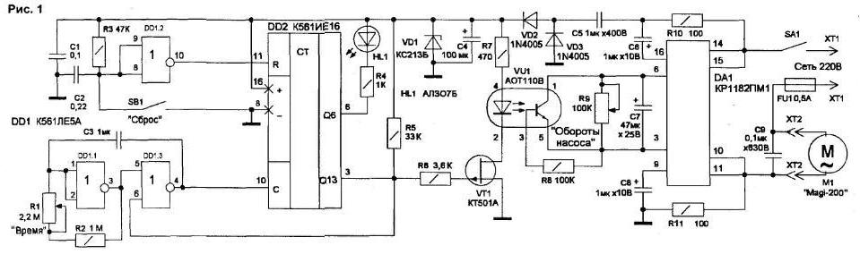
(click to enlarge)
To automatically shut off the pump when filling the tank, given its the mains supply, for security reasons, there are no level sensors, and time control (pump capacity - about 3 l/min). Relay time on two circuits DD1 and DD2 allows you to practice intervals time - from 15 minutes to 2 hours. For galvanic isolation of voltage from the electronic circuit device to shut off the pump passes through the optocoupler VU1. As the key is used, the amplifier is a field effect transistor VT1.
The generator of rectangular pulses is performed on two elements 2OR-NO chips DD1 (DD1.1 and DD1.3). The oscillator frequency is determined by the approximate formula:
f=0.44/RC;
where f is the frequency (in kilohertz); R is the total resistance of the resistors R1+R2 (in kiloomah); C - the capacitance of the capacitor C3
(microfarad). The minimum oscillator frequency is 0.2 Hz, the maximum 4,4 Hz (at zero resistance R1). The oscillator frequency does not depend on temperature and supply voltage (in the range from 4 to 15 In). Duty cycle pulses is equal to two.
The element DD1.2 is used to reset the counter DD2 in automatic mode At power on, the capacitor C2 is discharged, the 8 inputs. 9 D1.2 is a low level, respectively, the output DD1 10.2 - high, resets the counter DD2 input R. After charging of the capacitor C2 through the resistor R3 inputs DD1.2 appears a high level, the element switches, and low level at its output enables the counter DD2.
Chip DD2 contains a 14-bit asynchronous counter. The contents of the counter increases for each negative slope of the clock pulse. Output the signal is taken from the output 013 (output 3 DD2), although you can use any the output from Q9 to 013, by making changes in the operation of the generator.
When the pulse frequency 1,066 Hz "1" at pin 6 DD2 appears after one minute after zeroing. The multivibrator on DD1.1 and DD1.3 stops after the appearance high-level output Q13. The account can at any time be reset by pressing the button SB1. Readout control account is made on HL1 led. Every 8 pulses the led lights up, and the next 8 does not light. The pulse duration the multivibrator is set by the variable resistor R1.
The speed control of the pump motor is the chip DA1-phase the power controller. It consists of two thyristors, the management host and device thermal protection. Chip overload and overheating limits the power in load the Speed of the pump rather smoothly regulated when the voltage on the motor 80 to 240 V.
Low level output 3 DD2 during the account bypasses the voltage divider R5-R6, so field-effect transistor VT1 is closed. Current in stock transistor circuit no, the led of the optocoupler VU1 is not lit, so the chain collector-emitter the internal transistor of the Photocoupler has a high resistance and shunt resistor R9. The phase regulator DA1 opened, and the pump motor runs on full power.
At the end of the account at pin 3 DD2 there is a high level through resistor R5 opens the transistor VT1. Turns on the led of the Photocoupler and opens the internal transistor that bypasses conclusions 3 and 6 of chip DA1. The regulator DA1 is disabled and the load is gradually removed over time, dependent from the capacitance of the capacitor C7. The pumps are switched on after pressing the button SB1 is happening also smoothly that protects the mechanics from premature failure. Momentum the pump is regulated by a variable resistor R9.
Adjustments in the scheme virtually none. When the voltage at the device is not works (pump does not rotate HL1 led is not lit). The work begins with pressing the button SB1 "Reset". After short press the SB1 led will light and the motor-pump begins to rotate. Running multivibrator should produce the output 4 DD1.3 pulses of 1 s.
The power of the device is performed from the network according to the transformerless circuit with blanking the capacitor C5 via the rectifier diode VD2. VD3 and parametric the stabilizer Zener diode VD1. Current consumption - no more than 2 mA. Voltage the supply of chips shall not exceed 15 V.
The device is assembled on the circuit Board dimensions 115x45 mm (Fig.2).
Case size slightly exceeds the size of the circuit Board. Led HL1. button SB1, speed control R9 and the switch SA1 fuse FU1 installed on the front panel of the device. To connect the pump has a special the nest, which is located in any convenient place.
When setting up the scheme, it is desirable to feed from a laboratory source or separate adapter (12V/0.1 A)to comply with security measures.
Literature
Authors: V. Konovalov, A. Vanteev, Irkutsk.