


")

It is well known that protective and regulating compressor relay and the thermostat is the least reliable elements of the household refrigerating aggregates domestic production. In the most cases, the cause of failure is associated with a burn contact the protective pads of the node. The inability to change the contact forces to eliminate a fault banal installing the new relay. The combination of low reliability and the high cost of these nodes makes considerable merit in the establishment of their electronic counterparts. The proposed control unit performs the functions protective and regulating relay and thermostat.
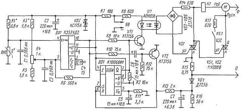
Schematic diagram of the control unit shown in the figure.
(click to enlarge)
The comparator at the shelter DA1 designed to compare two voltages: coming deliverer temperature RK1 and support, the value of which is determined by the position of the slider variable resistor R4. The resistor R6 is included in the chain of positive feedback defining the width of the hysteresis. Control voltage with the output OU DA1 (output 10) is supplied to the base of transistor VT1, operating in key mode and specifies the state of a thyristor optocoupler U1. and hence triac the starting node VS1. When the temperature in the refrigerating chamber at the outlet comparator high voltage level, which opens the transistor VT1. In the result turns on the triac VS1 and through the winding of relay K1 begins to flow a current of several amperes. Contacts To 1.1 of this relay are closed and through opened triac VS2 is connected to the network starting the winding of the compressor. After its normal running current is flowing through relay K1, is reduced to working values and triac VS2 closes. The use of the triac in the circuit starting the windings of the compressor reduces the current through the contacts To 1.1 and protects them from burnout.
The base of transistor VT1 is connected to an open collector output chip DD1. which has a threshold protective device. Current sensor this device is a resistor R15, included in the control circuit compressor. The voltage from the resistor R15 is supplied to the rectifier and VD1C7R16 then through the resistor R13 is the input of the precision Schmitt trigger on a chip DD1. The upper threshold of the trigger is determined by the voltage at its input Oia (pin 5). which, in turn, depends on the resistance of the resistor R1 1. When specified on the diagram the values and supply the trigger voltage of +7.5 V he triggered when the current of about 2 A. When you switch the Schmitt trigger the output the transistor opens, the same transistor VT1 is closed and the compressor shuts off from the network. In this state, the control device remains until then. while capacitor C7 charges up to the voltage corresponding to the lower threshold trigger DDI, i.e. within approximately 20 s. this is followed a new attempt to start the compressor.
When you turn on refrigerator due to the increase in temperature in the working volume of the device protection for 1…2 should not react to a significant excess operating current, provided by blocking it at this time. It provides cascade on the VT2 transistor. With the appearance of a positive voltage at the output comparator DA1 capacitor C6 begins to charge through a chain of R12. R10 and transition the base-emitter of the transistor VT2. The charging current opens the transistor VT2. and the security device is locked by connecting the inputs of the flip-flop DD1 (findings 2. 6) to a common wire at the time you specified above. Resistors R12. R2 provide secure closing VT transistors 1. VT2 in the absence of the Manager voltage.
The control unit is powered by a small DC voltage of +9 V. the consumed current does not exceed 25 mA.
In the device used fixed resistors C5-MW (R15) and MLT-0.125 (rest), AC - SDR-4A, a thermistor - MMT-4 (or any similar to the DC resistance at +20°C of about 1 kω). Capacitors C2. C7 - C50-29. C5. C6 - K53-4. other - any small-sized.
To simplify the design utilized surviving winding K1 and starting the contacts K1.1 from an old relay of the fridge.
Establishing correctly the circuit is reduced to a threshold setting triggering node protection selection resistor R11 (when working on the equivalent load) and simultaneously the selection of resistors R1, R3 to achieve the desired the temperature adjustment range. Operating current control devices is about 1 A, the current protection 2 A, the accuracy of temperature inside the refrigerating chamber is ±0,25°C.
The device is directly connected to the network, so you need to be very careful setting it up.
Design of device should not touch it elements during operation. It is best to mount it in fully closed plastic box with a lid at the bottom and seal the carton, for example, clay.
For isolation of the thermistor can be offered. To conclusions thermistor soldered flexible wires with a length of 0.6 m and place it in PVC tube with a length of about 1 m. to Bend the tube in half, make the open ends of the tube inside the body.
When you switch the device to the network must comply with the phasing plug, shown in the diagram. The common wire should not connect to the body of the refrigerator.
Author: D. Pankratiev, Tashkent, Uzbekistan