


")

At the cottage or the plot is always required to have a supply of water for economic needs. Keep the tank in the shower or reservoir for watering the plants filled to the required level will help you simple electronic machine.
Consider the operation of the device to the concept. If the water in the tank no either its level reaches the sensor E2, when you turn on the switch transistor Q1 VT1 is closed, relay K1 is de-energized, and through its normally closed contact pair K1.2 AC voltage goes to the pump motor, pumped water into the tank. Once the water level reaches the sensor E2, the base circuit of the transistor will be closed and it will open. Will trigger the relay and breaks contact K1.2, thereby breaking the power circuit of the motor of the water pump. At the same time the contact pair K1.1 connects to the base of VT1 sensor E3, providing open state of the semiconductor device as long as the water level (when her expenditure) falls below the sensor E3 (or E1) and the cycle of water injection again. Diode VD2 eliminates inductive interference that occurs when triggered relay K1. When you turn off Q1 controller abastecida, the pump pumping the water will stop.
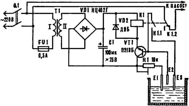
Schematic diagram of the regulator
The device incorporates an electromagnetic relay brand PE-US with weakened spring anchor; coil resistance is 90 Ohms, the operating current is 90 mA. Will also fit any other relay with sufficiently strong contactors, triggered at a voltage of 12-15 V, for example, RES-8 (passport RS4.590.064).
Transistor PB permissible to replace P, CT with any letter index. Radiator for it is made of a piece of aluminium angle flange width 40 mm.
Instead of a block CCG possible to assemble the rectifier in a bridge circuit of diodes with average rectified current 0.2 to 0.5 A, such as a series of D226, CD. Except indicated on the diagram of the device DB applicable any diodes D9, D226. Oxide the capacitor C1 by the capacity of 50-500 microfarads and a working voltage greater than 15 V - type K50-6.
Trimmer - SDR-9 or JS2-3b. Adjusting it to achieve the accurate actuation of the machine, as water in different areas has different conductivity. Suitable and constant resistor on the 1 - 2 Ohm power less than 0.5 watts.
The transformer T1 is low, the secondary winding voltage V. 12-15 May be used, for example, TCE-L from TVs or to wrap yourself in the yoke SLM 16X20. The primary winding has 2400 turns of wire sew-2 0,12, secondary - 136 turns of PEV-2 to 0.28.
The switch Q1 and switch TP1-2, or any two-pole switch on switching current of at least 2 A.
The regulator is installed in a dry, protected from the weather location (indoor), preferably closer to the input power wiring.
Sensors E1-E3 are made of stainless welding electrodes Ø 4 mm. Length E2 less than the other sensors 40-50 mm. They are mounted on epoxy glue in a plastic bracket that the two M4 screws fixed to the inner wall of the tank. The tail of the sensors in the attachment wires must be sealed with an epoxy adhesive or sealant.
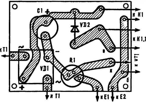
Circuit Board arrangement of elements
If the water tank is made of metal, you can do without the sensor E1. In this if the wire that goes from the resistor R1 is connected to the tank body using screw with washer.
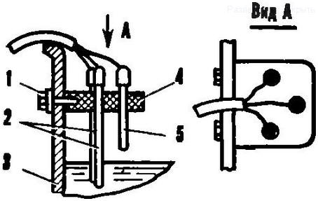
The knot of fastening of sensors: 1 - M4 screw 2 - sensors E1 and E3, 3 - tank, 4 - arm, 5 - sensor E2.
The device is easy to turn the water level switch. To do this, instead of a relay K1 include incandescent lamp at a voltage of 12 V. Lamp will glow when the water level reaches the sensor E2. Sensor E3 in this case not needed.
Author: A. Molchanov