


")

With this indicator can be used to detect the high-frequency source radiation and, in arbitrary units, set its level. The device will help to detect spy "bug", to determine the radiation from microwaves, cell phone, as well as, the presence of significant radiation in your apartment, for example, from the antenna of taxi service or cellular service, cable and terrestrial television, located on the roof of your block of flats.
Here is one real example - the residents of one of the apartments of "tower" began to complain the fact that in their apartment hesitantly, work cell phones, and in the hallway generally there is no connection completely. Another neighbor from the apartment above, complained the impossibility of reception of television and radio on the built-in antenna. I a third roommate was constantly having failures in the built-in computers of air conditioner and washing machine. Research apartments and part of the house with this indicator showed that a powerful source of interference is the cable reduce, laid on the ventilation shaft, from illegally installed on the roof aerial taxi service. Moreover, the apartment of the owner of a given service was on the first floor, and the cable is passed to the antenna through all 16 floors house, generously handing out the RF interference around the entrance.
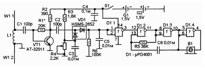
Does the indicator as follows. In the presence of RF radiation, the indicator emits a tonal sound. The sensitivity threshold set by the variable resistor R4, the angle of rotation of the handle which you can judge the level of RF radiation.
The antenna is a dipole consisting of two wires, each with a length of 75 mm. Between them is the input coil L1. The location is almost as the schematic diagram.
The adopted antenna signal from the coil L1 is supplied to RF amplifier for UHF transistor At-32011. Through this cascade, the instrument has high sensitivity.
Through the coupling capacitor C2 amplified signal to the detector diode Assembly part no HSMS-2856, in which microwave diodes. The detector is made according to the scheme with voltage doubler. Of the divider resistors RЗ and R4 is supplied to the diodes direct bias voltage. This voltage generates direct current, which increases the sensitivity of the detector, and generates a DC component at the output detector (resistor R6). By adjusting the value of this constant component (resistor R4) you can set the switching threshold of the element D1.1.
As the voltage on R6 exceeds the switching threshold D1.1 (a voltage at R6 - is the sum of a constant bias voltage with a voltage obtained from detector), the output D1.1 there is a logic zero, which leads to the start multivibrator D1.2-D1.3 and sounding the piezoelectric buzzer B1.
Details. Diode Assembly part no HSMS-2852 possible to replace virtually any two Microwave diodes or similar Assembly.
Replace the transistor VT1 can not offer, but I can state with full responsibility to assert that, under the condition of reducing the sensitivity of the transistor you can unsubscribe by connecting the capacitor C1 directly to the diodes VD1 Assembly (instead of C2). This version of the indicator (without VT1) was also made and tested. Subjectively, the sensitivity decreased five-fold, but remained sufficient to receiving a signal from cell phone at a distance of 2-3 meters.