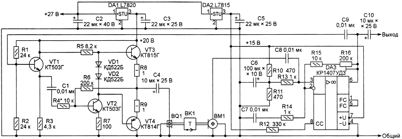
The described device is a transducer temperature - frequency discrete steps. The structure of this oscillator, positive feedback loop which contains the ultrasonic line of communication with in-sensitive element. They used polymer resettable fuse.
Due to the temperature dependence of both electric and acoustic properties of such a fuse is changed, the oscillation frequency of the oscillator. The sensor is designed for use in the composition of the admittance control devices the temperature of objects in hazardous environments, but may find application in other single-purpose systems, for example, in devices emergency fire alarm. Since the connection of the sensing element with an electronic unit acoustic, excluded the current flowing in the measuring circuit and the possibility of sparking in the controlled area.
Main technical characteristics
The operation temperature, °C, not more than 60...
The response time, with no more than 10...
Output voltage swing, V, not less than 5...
The voltage, V...27±3
Current consumption, mA, max 100...
The device consists of a sensing element included in the gap of the sound, forming an ultrasonic path between radiating and receiving piezoelectric transducers, power amplifier, pre-amplifier and the feedback circuit connecting the output of the pre amp with a power amp. The emitting transducer excites the acoustic sound waves that pass through the sensing element and reaches the receiving transducer, which converts them into an electrical signal. This signal, amplified pre-amplifier through the feedback circuit is input to the power amplifier.
As a result of positive feedback in the system be self-oscillations. The sensor probe is made of a material, the acoustic impedance of which changes sharply at a certain temperature. The result is an abrupt change in the oscillation frequency that is a sign of overheating. After the cause of overheating, the temperature sensitive element is reduced, the acoustic impedance of the communication line, and the oscillation frequency are returned to their original values - the sensor is again ready for operation. Sensor circuitry depicted in Fig. 1.

Figure 1
Transistors VT1-VT4 made amplifier. The gain of the voltage is determined by the ratio of the resistances of resistors R6 and R4. To the output of the amplifier is connected piezoelectric transducer radiating BQ 1, it is through the hearing tube and the sensing element BK1 acoustically linked with the receiving piezoelectric transducer WM. Capacitors C1 and C4 - separation. Diodes VD1 and VD2 set the bias voltage of transistors VT3 and VT4. The power amplifier is powered from the voltage regulator 20 In the chip DA1. Capacitor Sz - filtering in the power supply circuit.
Pre-amplifier is built on OS DA3. Since the supply of the operational amplifiers unipolar, with the help of resistors R10, R11 and R13 at its non-inverting input submitted by an offset equal to half the supply voltage. The capacitor C6 - locking in the bias circuits. Resistor R12 is set to the OS. Resistors R14-R16 and capacitor C7 form a negative feedback circuit that sets the gain of the pre amp. The output of this amplifier is connected to the input of the power amplifier through a capacitor C9, which closes a positive feedback. The condenser C10 - separation. The preamplifier is powered by the voltage regulator 15 on the chip In DA2. Capacitor C5 is the filter element in the food chain. The sensor element BK1 is a polymer resettable fuse Bourns MULTIFUSE company. Refrigerated structure polymer filling it resembles a crystal lattice. When heated it changes, so when it reaches a certain temperature, there is a leap not only the electric conductivity of the polymer, but also its acoustic impedance.
Most parts of the sensor are located on the breadboard with metallized holes, the installation is made of thin insulated wires. The fee is placed in a metal enclosure which can be set to the piezoelectric transducers. The sensor probe is located outside and connected to the transducer, the sound channel is U-shaped bend of steel wire with a diameter of 0.8 mm and a length of 1 m. the Opposite ends of the bell section is soldered to the working surfaces of the piezoelectric transducers. The sensing element is sealed in the gap of the sound at the point of bending.
The unit uses tantalum oxide capacitors K53-52, it is permissible to use other, for example K53-4. Ceramic capacitors - K10-176 (or km-3 km-6). Fixed resistors C2-33 (can be replaced - S2-23 MLT, ALT). Trimmer - SDR-39A (or SDR-37, RP1-48). Diodes CDB can be replaced by other silicon diodes, for example, from the series CD, KD521. Transistors CTG may be replaced by transistors of the same series or of silicon devices other series with the same parameters. CTG and CTG can be replaced by transistors of the same series or series CT and CT respectively. Instead of imported chips L7815, L7820 you can use the domestic circuit CREW and CREA respectively.
Piezoelasticity converters BQ 1, VM - chip three-terminal overseas production (estimated type FML-34.7 T-2.9B1-L). Resettable fuse MF-R025 is permissible to substitute similar firms Raychemf/Tyco or Little Fuse. The establishment of the sensor is to install a trimming resistor R16 of such gain in the positive feedback loop, in which there is sustainable generation, and the signal at the output of the power amplifier is a sinusoidal with small bilateral constraint. Increasing the temperature sensitive element BK1, fix the value at which an abrupt change in the oscillation frequency. You should ensure that the frequency returns to the original value during the cooling of the sensing element. In the author's version of the sensor, the frequency of the generated oscillations, a temperature sensitive element +20 °C was equal to 12.9 kHz, and when the temperature reaches +40 °C abruptly increased to 85,3 kHz.
Author: O. Ilyin, Kazan, Tatarstan; Publication: www.cxem.net


