Features of the metal detector
The sensitivity of this detector is improved by the use of the dependence of the length of the probe pulse from the intensity of the parcels themselves. In search generator introduced automatic frequency control. Any additional measures to stabilize the voltage and temperature compensation electronic components is not required.
Schematic diagram
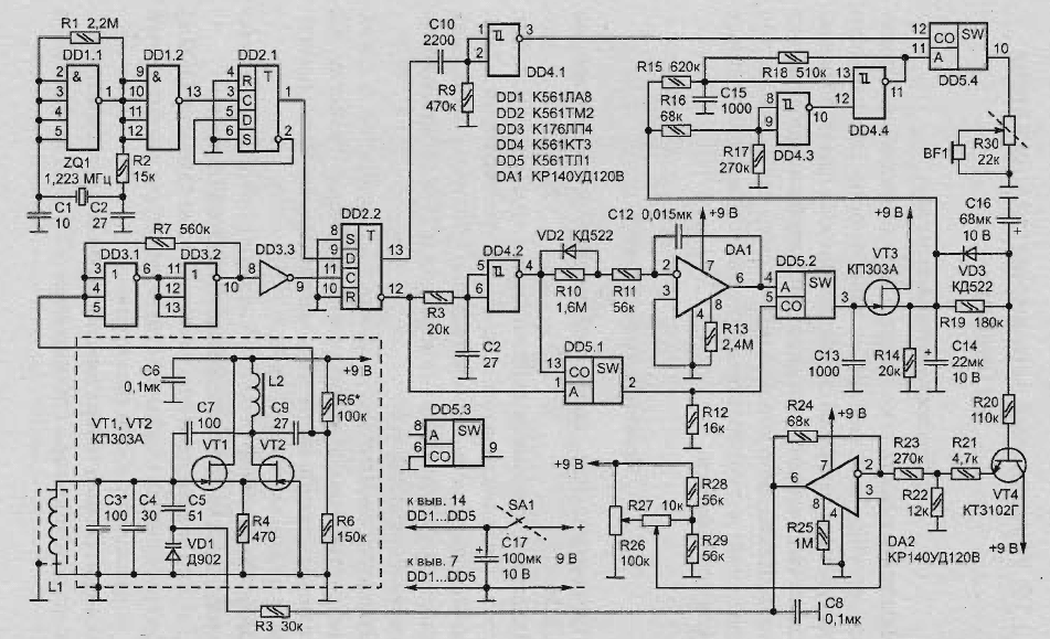
Schematic diagram of the device represented in Fig. 2.30.

Fig. 2.30. A schematic diagram of an improved version of the detector on the beat (click to enlarge)
The master oscillator is made on the element DD1.1. The frequency is stable quartz resonator ZQ1 included in the chain of positive feedback. For ensure the excitation of the generator when the power is resistor R1. The buffer element DD1.2 unloads the generator, and generates a signal with digital levels. The resistor R2 determines the degree of load and maximum power dissipated in the quartz resonator.
This generator can work with almost any resonators at a current consumption 500-800 mA. Reaching behind him, a frequency divider by two (element DD2.1) generates a signal with symmetrical meander necessary for normal operation of the mixer. Measuring the generator is assembled according to the scheme asymmetrical multivibrator (transistors VT1 and VT2). The yield on mode self-excitation circuit provides positive feedback on the capacitor C7.
Customizability elements are capacitors NW-C5, varicap VD1 and search coil-sensor L1. Generation is in the range from 500 kHz to 700 kHz, depending on available quartz resonator. Frequency drift of the oscillator during the first 10 s immediately after power is not more than 0.7 Hz (every 30 minutes up to 20 Hz).
For normal operation of the device is considered acceptable frequency deviation of 1 Hz for 1 min (without AFC). Issued by measuring the generator of sinusoidal signals, with amplitude of 1-1. 2 In, is supplied through coupling capacitor C9 to the elements DD3.1, DD3.2. These elements form rectangular pulses with digital levels and duty cycle 2. Resistors R5R6 form a divider that is required for normal operation of this plot diagram and element DD3.3 performs the role of a buffer stage. The signal is fed to the trigger DD2.2. There also comes the signal from the divider the reference oscillator.
The peculiarity of the flip-flop DD2.2 is such that if the inputs C and D this logic element come two pulse sequences that are close by frequency, the outputs signal is generated difference frequency with strictly a symmetrical square wave.
Direct and delayed, and at the same time proinvestirovannye (due to the circuit R8C11 and element DD4.2) the signals are summed at the key DD5.1 acting as logical element AND/OR. In this form, a short positive pulses recording for analog storage device (DD5.2. C13, VT3). Remove from the output DD4.2 the signal reaches the integrator, made by the classical scheme using elements VD2, R10-R11, DA1, C12.
Resistor R11 limits the current overcharging of the capacitor C12, unloading the output element DD4.2. The integrated signal through the key DD5.2 run pulses with DD5.1, is supplied to the storage capacitance C13. On this capacitor is formed and is retained with high accuracy to a new cycle record a voltage equal to the peak value of what is received from the integrator. Capacitor C14 smoothes the effect of type "step" that can occur when the abrupt change of frequency of the beats.
With source follower transistor VT3 signal:
- the comparator DD4.3;
- the controlled oscillator voltage;
- in the circuit loop of the AFC.
The divider R21R22 in conjunction with the feedback resistors R23 and R24 narrow the range of the control voltage to an amplitude of 1.2 V.
Operational amplifier DA2 compares the voltage that is set divider R26R29, and generates the voltage control variable capacitor VD1.
Adjustment of the metal detector
Resistor R26 is possible to set the starting point of capture AHR (SENSITIVITY) roughly, and resistor R27 - more accurately.
When you move the cursor R26 towards the extreme (upper or lower scheme) the situation can easily get out of the swath of IHD (±300 Hz), by mode work with beat frequency "one to one", making operation more flexible.
In fact, the AFC has two time constants (depending on which side changes the beat frequency). Special performance coil-sensor virtually eliminates the influence of the ferromagnetic properties of items found. Therefore, no impacts on the increase of the frequency of the search oscillator. Therefore, the AFC and the device in General work in all modes is quite correct.
Work GUN
GUN on the elements of DD4.4, R18, C15 converts voltage changes with frequency beat in the audio frequency. Configured by using the divider comparator R16R17 DD4.3 allows him to do in the area of maximum sensitivity when the beat frequency is in the range 0-70 Hz.
The signal from the VCO is fed to the input "A" of the mixer (key DD5.4). The input of "WITH" from logic element DD4.1 comes difference beat frequency. As a result the mixer output is present:
- or modulated by the beat frequency of the VCO signal;
- or just beat frequency.
Furthermore, the transition from one mode to another scheme automatically.
Variable resistor R30 is load and volume control, and combined with him SA1 switch power supply. The use of chip series and CMOS operational amplifiers operating in the micro mode, has reduced the current consumption of the scheme to the level of 6 mA, making the acceptable battery usage "Krone" as the power source.
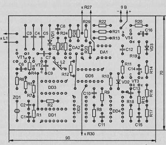
The location of elements on the Board shown in Fig. 2.31.

Fig. 2.31. The location of elements on the Board
Mounting frame-sensor detector
Technology and precision frame sensor very strong influence on the quality of the whole device. As a basis it is recommended to use a harness composed of eleven segments of wire sew-2 1.2 mm length 1100 mm. It should tightly wrap a layer of electrical tape to squeeze in an aluminium tube with internal the diameter of 10 mm and a length of 960 mm. Obtained the workpiece to shape rectangle 300 x 200 mm with rounded corners.
The end of the first wire, placed in an aluminum casing, electrostatic the screen sequentially soldered to the second wire and so on, until education peculiar to the 11-turn inductors. Soldering each other should be insulated with a paper tape and fill with epoxy resin, excluding the appearance of a closed loop through the bent frame tube.
It is desirable here to provide for any indoor high-frequency connector and suitable (non-metallic) mount for the handle, which can use one or two sections from a collapsible fishing rods. The cable that connects the frame with the block, better to use coaxial, television, for example, RK75.
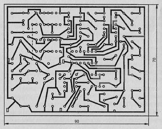
Almost all of the detector may be mounted on a printed circuit Board (Fig. 2.32) sided foil fiberglass.

Fig. 2.32. The printed circuit Board
Search generator is recommended to be placed in a shielding box made of tin.
Element base
The inductor L2 of the search generator has 150 turns of wire PEL-1 to 0.01. Winding you need to produce in bulk to the frame with a diameter of 4 mm and a length of 15 mm with ferromagnetic adjusted core NN. The inductance of this choke 1-1,2 mH.
The device uses capacitors CSR or CTC (CL, C4, C5), KLS or KM (C1, C2, C6-C13, C15), K50-6 or K53-1 (C14, C16. C17). Resistors - MLT 0,125, rigged R26, R27 suitable SP5-2 or SP-3.
As transistors VT1 and VT2, for example, suitable CPB (G). In place VT3 acceptable CP or CP with any letter, CTG (VT4) to replace CTE. Quartz - 1.0-1.4 MHz. The varicap D can be replaced by D.
Author: Stafiychuk Y.


